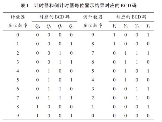
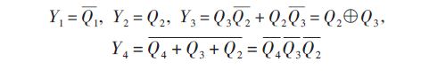
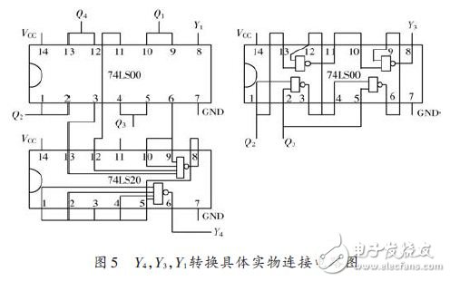
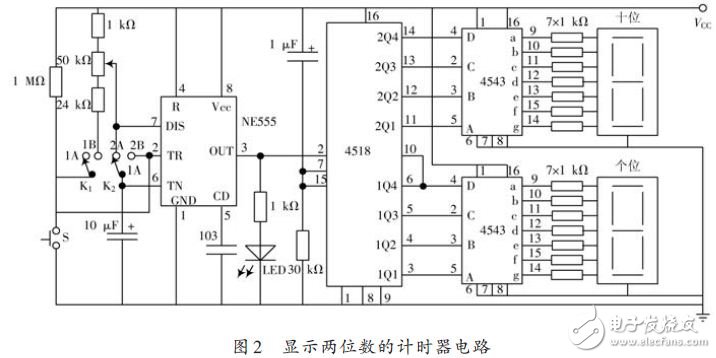
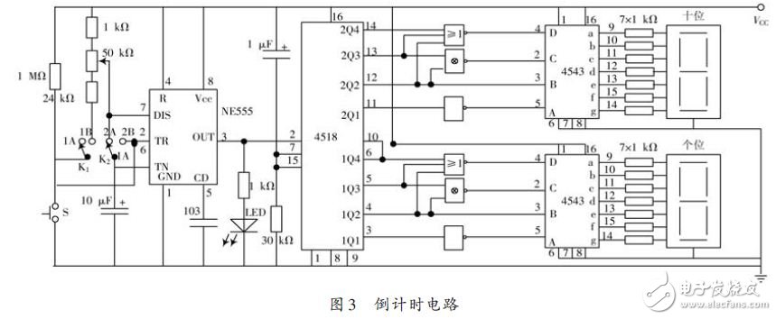
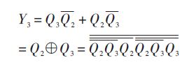
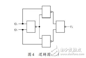
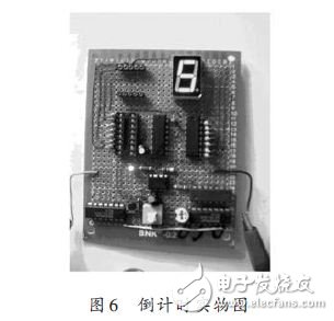
Abstract: There are many design methods for the countdown timer. This article introduces a design scheme that implements the timer to become a countdown timer. The solution realizes that all timers become countdown timers through clever design methods. Moreover, the design method is applicable to all decimal timers, and has good universality and practicality. 0 Preface The general idea that the timer becomes a countdown timer is to change the counting chip in the timer, or to reset the function of the chip. In fact, the result displayed by the display can be "reversed" to display, thereby achieving the purpose of counting down. 1 idea of ​​program design The result of each bit of the timer is an incremented value, such as 0.1.2.3.4.5.6.7.8.9, and the countdown timer shows a decreasing value, such as 9.8.7.6.5.4.3.2.1.0, then just use the appropriate The logic circuit completes this display result conversion and can turn the timer into a countdown timer. First, look for the logical relationship between the timer display result and the display result of the countdown timer. Table 1 lists the BCD codes corresponding to the display results of the timer and the countdown timer. From this table, the BCD code of the timer and the countdown timer can be easily found. The lowest bit in the middle Q1 is opposite to Y1; Q2 is the same as Y2; the relationship between Q3 and Y3: Y3 of the countdown timer is the exclusive OR of the timer Q3, and Q2; the relationship between Q4 and Y4: the Y4 bit of the countdown timer is The opposite value of the sum of Q4, Q3, and Q2 of the timer is also equal to the non-reciprocal of Q4, Q3, and Q2. The above logical expression is: The logical diagram of the above logical relationship is shown in Figure 1. Therefore, as long as the circuit capable of completing the above logical conversion relationship is selected, the design from the timer to the countdown timer can be realized. As shown in FIG. 2, a two-digit timer circuit is displayed, and after adding the above conversion circuit, it becomes as shown in the figure. Countdown circuit shown in 3. 2 realization of the design plan 2.1 with two 74LS00 and 74LS20 chips The former is four two-input NAND gates, one is used to complete the conversion of Y1 and the non-generation of Q4, Q3, and Q2. The latter is two four-input NAND gates, which are used to re-enter Q4, Q3, and Q2. Get Y4, another 74LS00 has four NAND gates, which can be based on the following logical relationship: Its logic diagram is shown in Figure 4. It is known that the operation of the XOR gate can be completed, that is, the conversion of Y3 can be completed. The connection circuit diagram of the above Y4, Y3, Y1 conversion concrete object is shown in FIG. 5. Figure 6 shows the physical graph of the countdown timer. 2.2 with 74LS27 and 74LS86 chips The former is two four-input NOR gates for completing the conversion of Y4 and Y1, the latter being four two-input XOR gates for Y3 conversion. 3 Conclusion In this paper, a design scheme that implements a timer becomes a countdown timer, which realizes that all timers become countdown timers through a clever design method. The design method does not need to change the original counter circuit, but the counter is turned into a down counter by embedding the designed circuit in front of each decoder on the basis of the original circuit. The countdown timer is widely used in basketball games, traffic booths and other fields, which proves that the scheme has good universality and practicability. 25.2VDC for 6S Battery Charger
The KSPOWER brand 25.2VDC for 6S Battery Charger is one black or white color, accepts universal input 100-240V AC voltage and provides the complete power transformer solutions covering the dc output wattages ranging from 5 watts to 100 watts and the output current ranging from 100ma to 5000ma single output chargers. The desktop battery charger features high energy efficiency level VI and reliability, with quick charging function used for 18650 batteries and li-ion batteries, etc. The dc in charger adopts constant voltage and constant current mode and accepts wall plug-in version, desktop version, and cord to cord version, all available with 2 colors LED indicator for charging status(Green and Red light). The travel battery charger solutions also includes class I and class II installations, equipped with three standard AC inlets (IEC320-C14, IEC320-C6, IEC320-C8) and different kinds of AC plugs options.
External Battery Charger,universal battery charger,travel battery charger,18350 battery charger,ac dc charger Shenzhenshi Zhenhuan Electronic Co., Ltd , https://www.szzhpower.com