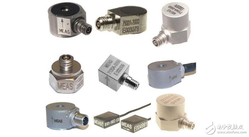
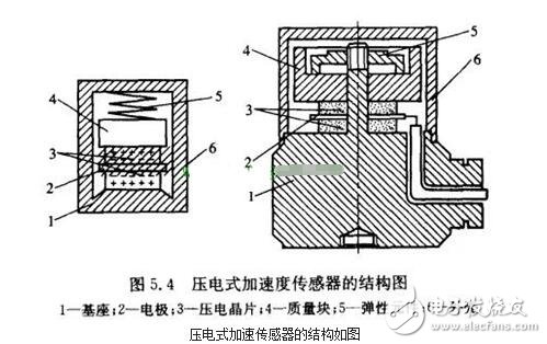
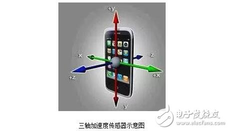
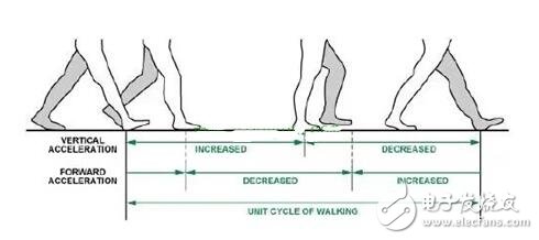
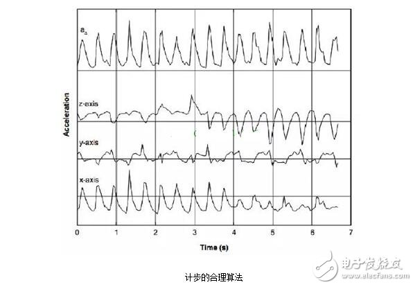
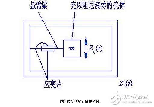
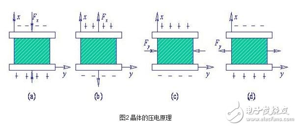
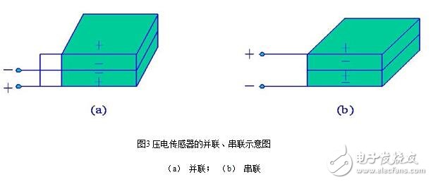
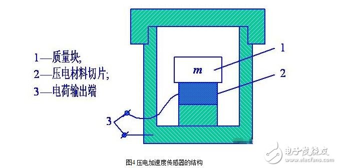
An acceleration sensor is a sensor that measures acceleration. It usually consists of mass, damper, elastic element, sensitive component and adaptive circuit. During the acceleration process, the sensor obtains the acceleration value by using Newton's second law by measuring the inertial force of the mass. Depending on the sensor's sensitive components, common accelerometers include capacitive, inductive, strain, piezoresistive, and piezoelectric. The acceleration sensor comprises a silicon diaphragm, an upper cover and a lower cover, and the diaphragm is placed between the upper cover and the lower cover and bonded together; the one-dimensional or two-dimensional nano material, the gold electrode and the lead are distributed on the diaphragm, and The wire is extracted by a pressure welding process; the industrial field vibration sensor is mainly a piezoelectric acceleration sensor. The working principle is mainly for the piezoelectric effect of the piezoelectric sensitive component to obtain a charge amount or a voltage amount proportional to vibration or pressure. At present, the industrial field typically uses an IEPE type acceleration sensor and a built-in IC circuit piezoelectric acceleration sensor, and the sensor outputs a voltage signal proportional to the amount of vibration. Piezoelectric Piezoelectric accelerometers are also known as piezoelectric accelerometers. It is also an inertial sensor. The principle of a piezoelectric accelerometer is to use the piezoelectric effect of a piezoelectric ceramic or a quartz crystal. When the accelerometer is vibrated, the force that the mass is applied to the piezoelectric element also changes. When the measured vibration frequency is much lower than the natural frequency of the accelerometer, the change in force is proportional to the measured acceleration. Piezoresistive Based on the world's leading MEMS silicon micromachining technology, piezoresistive accelerometers are small in size, low in power consumption, easy to integrate in various analog and digital circuits, and are widely used in automotive crash experiments, test instruments, equipment vibration monitoring, etc. field. Capacitive The capacitive acceleration sensor is a capacitance sensor based on the principle of capacitance. Capacitive accelerometers/capacitive accelerometers are relatively common accelerometers. There are no alternatives in some areas, such as airbags, mobile phone devices and so on. Capacitive accelerometers/capacitive accelerometers use a microelectromechanical system (MEMS) process that becomes economical in mass production, thus ensuring lower costs. Servo type The servo-type accelerometer is a closed-loop test system with good dynamic performance, large dynamic range and good linearity. The working principle, the vibration system of the sensor is composed of “mk†system, which is the same as the general accelerometer, but the mass m is followed by an electromagnetic coil. When there is acceleration input on the base, the mass deviates from the equilibrium position. The displacement sensor detects and converts it into a current output after being amplified by a servo amplifier. The current flows through the electromagnetic coil to generate an electromagnetic restoring force in the magnetic field of the permanent magnet, so as to maintain the mass in the original equilibrium position in the instrument housing, so The servo acceleration sensor operates in a closed loop state. Thanks to the feedback function, the anti-interference ability is enhanced, the measurement accuracy is improved, and the measurement range is expanded. The servo acceleration measurement technology is widely used in inertial navigation and inertial guidance systems, and is also used in high-precision vibration measurement and calibration. The principle of the line accelerometer is the principle of inertia, that is, the balance of force, A (acceleration) = F (inertial force) / M (mass) We only need to measure F. How to measure F? Use electromagnetic force to balance this force. It is possible to obtain the relationship of F to the current. Just experiment to calibrate this scale factor. Of course, the intermediate signal transmission, amplification, and filtering are the things of the circuit. Modern technology requires acceleration sensors to be inexpensive, superior in performance, and easy to mass produce. In areas such as military, space systems, scientific measurement, etc., it is necessary to use an acceleration sensor that is small in size, light in weight, and stable in performance. Accelerometers manufactured by conventional processing methods are difficult to fully meet these requirements. Micro-acceleration sensors fabricated using emerging micromachining technology have emerged. The sensor is small in size, light in weight, low in power consumption, fast in starting, low in cost, high in reliability, and easy to digitize and intelligent. Moreover, since the micromechanical structure is precise, reproducible, easy to integrate, and suitable for mass production, its performance and price ratio are high. It is foreseeable that it will dominate the accelerometer market in the near future. The micro-acceleration sensor is in the form of piezoresistive, piezoelectric, and capacitive. Piezoelectric sensors use the principle of a spring mass system. The sensitive core mass is subjected to a vibration acceleration to generate a force proportional to the acceleration, and the piezoelectric material is subjected to the force to form a charge signal proportional to the force along the surface thereof. Piezoelectric accelerometers are the most widely used vibration measuring sensors because of their large dynamic range, wide frequency range, ruggedness, low external interference, and the ability of piezoelectric materials to generate charge signals without any external power supply. Although the piezoelectric accelerometer has a simple structure and a long history of commercial use, its performance parameters are closely related to material characteristics, design and processing technology, so the actual parameters of the performance of similar sensors sold on the market and their stability. And the consistency is very different. Compared with piezoresistive and capacitive, the biggest drawback is that piezoelectric accelerometers cannot measure signals at zero frequency. The structure of the piezoelectric acceleration sensor is shown in the figure. A metal foil is sandwiched between two silver-plated piezoelectric wafers (quartz crystal or piezoelectric ceramic), and lead wires for output signals are taken out. A mass is placed on the piezoelectric wafer and a pre-compression load is applied to the piezoelectric element with a hard spring. The static preload should be much larger than the maximum dynamic stress that the sensor can withstand during vibration and shock testing. Thus, when the sensor moves upward, the inertial force generated by the mass increases the compressive stress on the piezoelectric element; conversely, when the sensor moves downward, the compressive stress of the piezoelectric element decreases, thereby outputting a power proportional to the acceleration. signal. The entire assembly of the sensor is mounted on a primary base and is sealed with a metal housing. In order to isolate any strain of the test piece from being transmitted to the piezoelectric element, the pedestal is large in size. The base of the sensor is rigidly connected to the test piece during testing. When the vibration frequency of the test piece is much lower than the resonant frequency of the sensor, the sensor output charge (or voltage) is proportional to the acceleration of the test piece, and the acceleration can be measured by the charge amplifier or the voltage amplifier. The sensitive core of the strain piezoresistive accelerometer is a resistance measuring bridge made of semiconductor material, and its structural dynamic model is still a spring mass system. The development of modern micromachining manufacturing technology has made the design of piezoresistive sensitive cores very flexible to suit a variety of different measurement requirements. In terms of sensitivity and range, from low-sensitivity and high-range impact measurement to DC high-sensitivity low-frequency measurement, there are accelerometers in the form of piezoresistive. At the same time, the piezoresistive accelerometer can measure the frequency range from DC signal to high frequency measurement with high stiffness and measurement frequency range up to several tens of kilohertz. The ultra-small design is also a bright spot for piezoresistive sensors. It should be noted that although the design and application of the piezoresistive sensitive core is very flexible, it is generally used in a smaller range than a piezoelectric sensor for a particular design of a piezoresistive core. Another disadvantage of piezoresistive accelerometers is that they are greatly affected by temperature, and practical sensors generally require temperature compensation. In terms of price, the cost price of piezoresistive sensors used in large quantities has great market competitiveness, but the manufacturing cost of special sensitive cores will be much higher than that of piezoelectric accelerometers. The structural form of the capacitive accelerometer generally also uses a spring mass system. When the mass is moved by the acceleration, the gap between the mass and the fixed electrode is changed to change the capacitance value. Compared with other types of accelerometers, capacitive accelerometers have high sensitivity, zero frequency response, and good environmental adaptability, especially due to the small temperature; but the disadvantages are that the input and output of the signal are nonlinear. The range is limited, affected by the capacitance of the cable, and the capacitive sensor itself is a high-impedance signal source, so the output signal of the capacitive sensor often needs to be improved by the subsequent circuit. In practical applications, capacitive accelerometers are used more frequently for low-frequency measurements, which are less versatile than piezoelectric accelerometers and cost much higher than piezoelectric accelerometers. Acceleration sensors can be used in control, handle vibration and shaking, instrumentation, automotive brake start detection, seismic detection, alarm systems, toys, structures, environmental monitoring, engineering vibration measurement, geological exploration, railways, bridges, dam vibration Test and analysis; mouse, high-rise building structure dynamics and safety to defend vibration reconnaissance. At present, most devices provide acceleration sensors that can detect various directions. Taking the iOS device as an example, we analyzed the characteristics of its three-axis acceleration sensor (x, y, z axis represents the direction as shown). They are used to detect acceleration changes in three directions in a person's walking. During horizontal walking, the user's vertical and forward accelerations will change periodically as shown. In the action of walking and closing the foot, since the center of gravity touches the ground with one foot, the vertical direction acceleration tends to increase in the positive direction, and then continues to move forward, and the center of gravity moves down to the bottom of the foot, and the acceleration is reversed. The horizontal acceleration decreases when the foot is closed and increases when it steps. Reflected in the chart, it can be seen that during walking, the acceleration and time generated by vertical and forward are roughly a sinusoid and there is a peak at a certain point. Among them, the acceleration in the vertical direction changes the most. By detecting and calculating the peak value of the trajectory and determining the acceleration threshold value, the number of steps of the user motion can be calculated in real time, and the user walking distance can be further estimated. Because the user may hold the device by hand during exercise or put the device in a pocket. Therefore, the orientation of the device is not fixed. To this end, we can obtain a sinusoidal trajectory of a walking motion by calculating the vector length of the three accelerations. The second step is peak detection. We record the length of the last vector and the direction of motion. By changing the length of the vector, we can determine the direction of the current acceleration and compare it with the direction of the last saved acceleration. If it is the opposite, that is, just after the peak state, enter the step logic to perform the step, otherwise discard. By accumulating the number of peaks, the pace of the user's walking can be obtained. Finally, it is to disturb. Handheld devices have some low-amplitude and fast twitching states, or what we call a hand-shake, or a prank user wants to simulate a person walking by briefly shaking the device in a short time. If the interference data is not removed, it will affect the pace. The exact value of this interference can be filtered by adding a threshold and a step frequency judgment to the test. The principle of the strain sensor acceleration test is shown in Figure 1. It tests the inertia force to induce the deformation of the elastic sensitive component. 1. Piezoelectric effect and piezoelectric material Fig. 2 shows a state in which a charge generation direction is generated when a crystal slice is subjected to pressure and tension in the z-axis and y-axis directions. 2. Structure and characteristics of piezoelectric sensors Piezoelectric sensors are generally bonded by two or more piezoelectric crystals. Since the piezoelectric wafer has a charge polarity, the connection is divided into two types: parallel and series (as shown in Fig. 3). 3. Application of piezoelectric sensors The structure of the piezoelectric acceleration test sensor is shown in Figure 4. Dongguan Yangyue Metal Technology Co., Ltd , https://www.yyconnector.com