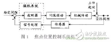
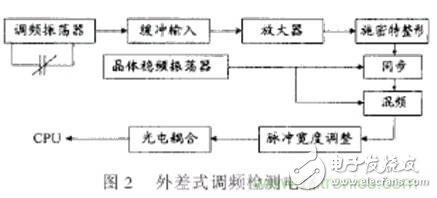
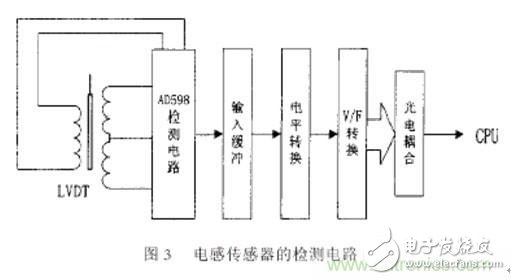
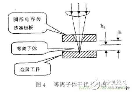
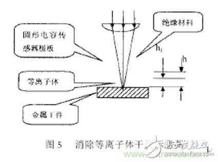
The focus position of laser focus cannot be directly measured, but it can be detected by indirect method. For a laser cutting system, the focus position is determined by the optical focus of the focusing lens, so that the position of the focusing lens is constant (regardless of the thermal effect of the focusing lens) in a certain case, so it can be detected by detecting the focusing lens and The relative position between the processing objects indirectly detects the positional relationship between the focus and the object being processed. The relative position between the laser focus and the object to be machined can be detected by an inductive displacement sensor and a capacitive sensor, each having advantages and disadvantages in use. The inductive sensor has a low response frequency and is not suitable for high-speed machining and non-contact detection applications such as dimensional processing. The capacitive sensor has advantages of fast response and high detection accuracy, but it is nonlinear and easy to use. It is influenced by the interference of plasma clouds and spray residue generated during the laser cutting process. This article will systematically discuss the path of the laser focus position error in the laser cutting process and the composition of the automatic elimination error control system. On this basis, the deficiencies and overcoming methods of the two sensor detection system components as well as their practical use are discussed. In the laser cutting process, there are many factors that change the relative position between the focal point and the surface of the workpiece. The workpiece surface is uneven, the workpiece is clamped, the geometrical error of the machine tool and the deformation of the machine under load, the workpiece is Thermal distortions during processing can cause deviations between the laser focus position and the ideal reference position (programmed position). Some errors (such as machine tool geometric errors) have regularity and can be compensated by quantitative compensation methods, but some errors are random errors that can only be eliminated by online detection and control. These errors are: 1.1 Workpiece geometry error The laser cutting object is a plate or a cover-type part. Due to various reasons, the surface of the processing object has undulations, and the surface of the thin plate part is deformed due to the thermal effect during the cutting process. In the case of laser processing, the surface of the cover will also be uneven during the press forming process. All of these will produce random changes in the position and ideal position of the laser focus and the surface of the object to be machined. 1.2 Errors generated by the workpiece clamping device Laser-cutting workpieces are placed on a needle-shaped table. Due to machining errors, wear between the workpiece and the laser, the needle bed may be uneven. This unevenness will also result in a thin steel plate and laser focus. The random error in the position. 1.3 Errors produced by programming In the process of 1D laser cutting, the machining trajectories on complex surfaces are fitted by straight lines, arcs, etc. These fitting curves and actual curves have certain errors. These errors make the actual focus and the processing object. The relative position of the surface and the ideal programming position produce some errors. Some teaching programming systems introduce some deviations. As shown in Figure 1, the laser cutting focus position online detection and control system consists of a controller, a detection system, and an execution device. According to the relationship between the focus position detection control system and the system, the focus position detection control system is divided into two types: independent type and integrated type. The independent focus position detection and control system uses a separate coordinate axis for the compensation control of the focus position error. The mechanical structure is complex and the cost is high, but it can be used with various CNC systems and laser cutting machine tools. The integrated type uses a feed axis of a laser cutting machine (for plane machining) or a combination of multiple feed axes (for a 1-dimensional cutting process) to compensate for focus position error. This method has the advantages of simple structure, low cost and easy adjustment, but requires the same design as the numerical control system, and has a higher requirement for the openness of the numerical control system. 2.1 Capacitance sensor detection circuit As shown in FIG. 2 , the capacitance sensor detection circuit converts the capacitance signal into a pulse signal of a corresponding frequency through a pair of a tuned oscillator, a signal amplifier, a crystal frequency stabilization oscillator, a synchronization circuit, a mixer circuit, a signal processing circuit, and the like. The signal is frequency sampled and processed to obtain the corresponding capacitance. The capacitance here is the capacitance formed by the two plates between the cutting nozzle and the cutting object. Obviously, the capacitance is related not only to the area of ​​the two plates but also to the spacing between the plates and the plates between the plates. This interval is related to the interval between the laser focusing lens and the workpiece, that is, the interval between the laser focus and the workpiece, so the capacitance approximation and the focus position are related to the interval between the cutting objects. This is the principle of the capacitive sensor detecting the focus position. It can be seen from the figure that the relationship between frequency and focus position error is nonlinear and must be linearized by the computer. At the same time, because the capacitance is also related to the medium between the plates, the detection results are easily affected by the plasma clouds and the slag generated during the process and must be overcome. 2.2 Inductive sensor detection circuit As shown in FIG. 3, since the latest large-scale integrated circuit is adopted, the detection circuit of the inductive sensor is relatively simple, and the integrated circuit adopts a new modulation and demodulation method and algorithm, which reduces the previous method of detecting heterodyne FM detection circuit. Because of the influence of phase angle, frequency and amplitude drift of the sensor's excitation signal on the detection result, the detection precision and stability are greatly improved. After the sensor signal is processed, a voltage signal proportional to the displacement of the sensor probe is obtained, converted into a corresponding frequency signal through a conversion circuit, and a position error signal of the focus is obtained through computer processing. Due to the inherent characteristics of the inductive sensor, the frequency of the signal to be measured has a certain limit (several hundred), which is not suitable for high-speed machining applications. At the same time, since it is a contact-type detection method, it can only be used in plane machining applications. At the moment when the workpiece has not been cut through, the laser interacts with the metal, creating a cloud-like plasma between the nozzle and the processing object, altering the medium between the capacitive plates, and thus interfering with the capacitive sensor. During the normal cutting process, the assist gas blows the plasma away from the slit, which has little effect on the capacitive sensor. However, if the processing speed is too fast and the cutting is just started, the plasma cloud will be generated around the laser irradiation point due to the workpiece not being completely cut. This will cause interference to the capacitive sensor, even if the sensor fails to work properly in severe cases, which seriously affects the processing quality. FIG. 4 is a schematic diagram of plasma interference. According to the principle of electromagnetism, the capacitance between two adjacent plates is C = εS/h, where ε - the dielectric constant between the plates is generally (1), S - the plate is relatively Effective area, h---Interval between two plates, If there is no interference from the plasma, then the capacitance measured according to equation (1) is inversely proportional to the distance between the plates (nozzles and objects), from the capacitance It is convenient to find the spacing between two plates, and then find the relative position between the focus and the object to be machined. However, when there is plasma or spray residue between the nozzle and the object to be processed, the dielectric between the capacitor plates is not air, and its dielectric constant changes. By the principle of capacitance principle, the capacitance between two plates is: C''''=ε S1 /[(h-h1)+h1ε/ε1 ]+εS2/h (2), where ε1—dielectric constant of the plasma, h1—the thickness of the plasma cloud S1 + S2 =S are the areas with plasma clouds or slag spray and areas without plasma clouds or slag spray. If the plasma cloud is evenly distributed within a certain height range between the nozzle and the object to be processed, the capacitance The interval between the two plates measured by the sensor is: h''''=(h-h1)+ h1ε/ε1 (3) The theoretical error of detection: Δh = h''''-h = h1 (ε/ε1 -1) (4) From equation (4), the magnitude of the error is determined by the thickness of the plasma cloud between the plates and the dielectric constant of the plasma. The plasma dielectric constant has a very large value, which can reach the order of 105. Therefore, it can be seen from equation (4) that the influence of the plasma cloud or spray residue on the detection results is very large. The literature [2~4] shows that if the thickness of the plasma cloud is 1~2mm, it is detected by the capacitive sensor. The theoretical error of the spacing between the two plates also reaches 1 to 2 mm, apparently failing to reach the accuracy index of the laser focus position detection (±0.2 mm). The interference of the plasma with the capacitive sensor is due to the plasma changing the medium between the capacitive plates. Therefore, in order to eliminate the interference of the plasma to the capacitive sensor, it is necessary to make the medium between the two plates of the capacitor not be affected by the plasma, so that the center hole of the circular ring plate can be enlarged and the capacitive sensor can be moved to the plasma cloud. Method to achieve. (1) To eliminate the effect of plasma on the capacitance, place the plasma outside the plates of the capacitive sensor. Considering that the plasma cloud is distributed around the cutting point, it can be as shown in Fig. 5: The diameter of the center hole of the circular ring plate is expanded to 2~3mm and embedded in the insulation-resistant high-temperature ceramic material due to the capacitance sensor. The plate is hollow. Without considering the edge effect, the plasma cloud around the irradiation point does not affect the sensor capacitance and the detection value. Therefore, this method can effectively reduce the interference effect of the plasma cloud. (2) For plane laser cutting, it can also be measured indirectly by mechanical transmission method. That is, by a mechanical device following the movement of the object to be processed, the upper end of the mechanism and the detection sensor form a plate, and the position between the laser focus and the object to be machined is indirectly detected by detecting the interval between the sensor and the mechanism. This method can avoid the influence of ion cloud and spray residue on the detection precision to the maximum extent, and it also takes advantage of the rapid response of capacitive sensors. Laser focus position detection and control is one of the key technologies of laser cutting processing. For fast cutting processing, the accuracy and rapidity of focus position detection will directly affect the control precision and processing quality of the focus position, and the capacitive sensing has high detection sensitivity. The advantages of fast response can overcome the non-linearity of the computer system through linearization; through the special sensor structure, the influence of plasma clouds and spray slag generated during the machining process on the detection results is eliminated, and the laser cutting process system is improved. Effect. India Modular Wall Switch And Socket India Modular Wall Switch And Socket,India Modular Wall Switch,India Modular Wall Socket,Best India Modular Wall Switch ZHEJIANG HUAYAN ELECTRIC CO.,LTD , https://www.huayanelectric.com