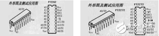
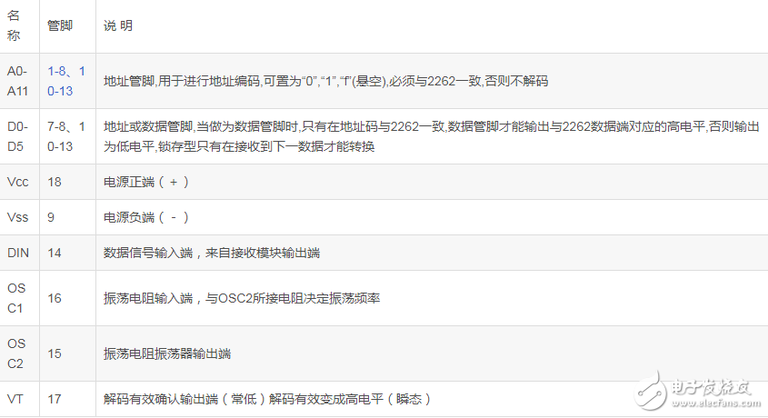
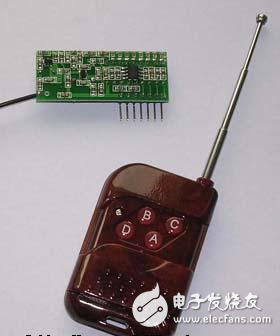
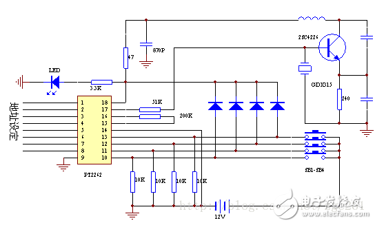
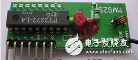
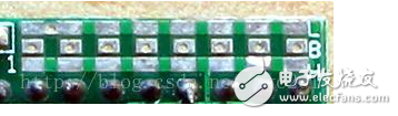
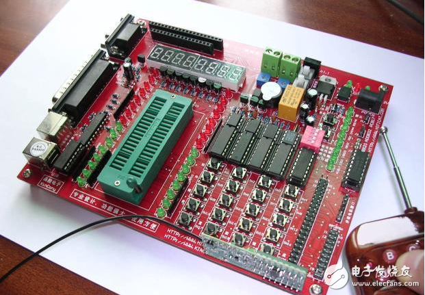
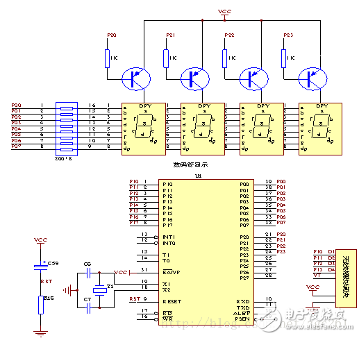
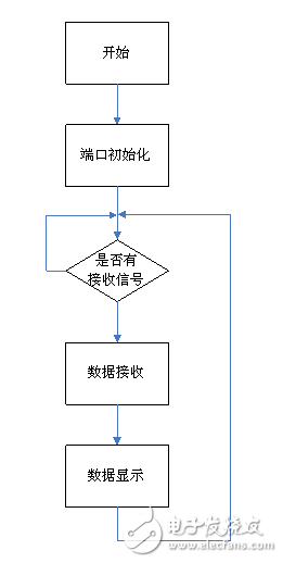
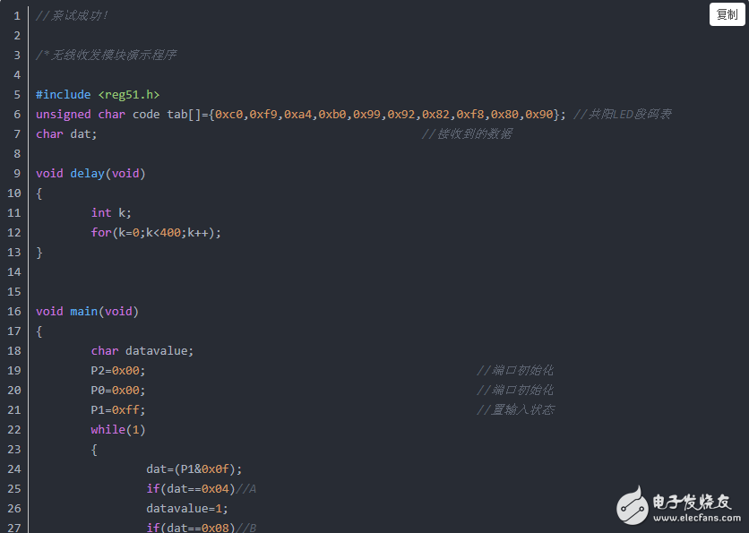
315M wireless module parameter introduction The working frequency of the data transmitting module is 315M, and the SAW frequency stabilization is adopted by the sound meter resonator, and the frequency stability is extremely high. When the ambient temperature changes between -25 and +85 degrees, the frequency drift is only 3ppm/degree. It is especially suitable for multiple send and receive wireless remote control and data transmission systems. The frequency stability of SAW resonators is second only to crystals, while the frequency stability and consistency of general LC oscillators are poor. Even if high-quality fine-tuning capacitors are used, temperature differences and vibrations are difficult to ensure that the adjusted frequency is not Offset will occur. The transmitter module is not equipped with an encoding integrated circuit, but a data modulation transistor Q1 is added. This structure makes it easy to interface with other fixed encoding circuits, rolling code circuits and single-chip microcomputers without considering the operating voltage and output amplitude of the encoding circuit The size of the signal value. For example, when using coding integrated circuits such as PT2262 or SM5262 to connect, directly connect their data output pin 17 to the input of the data module. The data module has a wide operating voltage range of 3-12V, and the transmitting frequency is basically unchanged when the voltage changes, and the receiving module matched with the transmitting module can receive stably without any adjustment. When the transmitting voltage is 3V, the transmission distance in the open area is about 20-50 meters, and the transmitting power is small. When the voltage is 5V, it is about 100-200 meters, when the voltage is 9V, it is about 300-500 meters. When the transmitting voltage is 12V, it is The best working voltage has good emission effect, the emission current is about 60 mA, the transmission distance is 700-800 meters in the open area, and the emission power is about 500 mW. When the voltage is greater than 12V, the power consumption increases, and the effective transmission power no longer increases significantly. This set of modules is characterized by relatively large transmitting power and relatively long transmission distance, which is more suitable for communication under harsh conditions. The antenna is best to use a 25 cm long wire, and it is best to be erected during long-distance transmission. Because of the influence of many factors during radio signal transmission, the general practical distance is only half of the nominal distance or even less. This requires development. note. The data module uses ASK modulation to reduce power consumption. When the data signal stops, the transmission current drops to zero. The data signal and the input terminal of the transmission module can be connected with resistance or directly instead of capacitive coupling, otherwise the transmission module will not work normally. The data level should be close to the actual working voltage of the data module to obtain a higher modulation effect. It is best to install the transmitter module vertically on the edge of the motherboard, and it should be more than 5mm away from the surrounding devices to avoid the influence of the distributed parameters. The transmission distance of the module is related to the frequency and amplitude of the modulation signal, the transmission voltage and battery capacity, the sensitivity of the transmitting antenna, the receiver, and the receiving and sending environment. Generally, the maximum transmission distance in an open area is about 800 meters. In the case of obstacles, the distance will be shortened. Due to the refraction and reflection in the radio signal transmission process, some dead and unstable areas will be formed. Different receiving and sending environments will have different Sending and receiving distance. Here is the most commonly used 315M transmitter chip XC4388 on the market. [1] The chip includes a power amplifier, monostable circuit and a phase-locked loop controlled by an internal voltage-controlled oscillator and loop filtering. The monostable circuit is used to control the phase-locked loop and the power amplifier so that it can be quickly started during operation. XC4388 has an automatic standby function, the standby current is less than 1uA; few external components are required, and the frequency range is 250MHz ~ 450MHz. PT2262/PT2272 wireless module working principle PT2262/2272 is a low-power and low-cost general-purpose encoder/decoder circuit manufactured by Taiwan Pucheng Company in a CMOS process. It is currently one of the most commonly used chips for address coding recognition in wireless communication circuits. PT2262/2272 can have up to 12 bits (A0-A11) three-state (floating, connected to high level, connected to low level) address setting pins, any combination can provide 531441 address codes. PT2262 can have up to 6 bits (D0-D5) data terminal pins. The set address code and data code are serially output from pin 17 (Dout), which can be used for wireless remote control transmitter circuits. The pin arrangement of PT2262 and PT2272 is shown in Figure 2. For the encoder PT2262, a total of 6 wires from A0 to A5 are address wires, and a total of 6 wires from A6 to A11 can be used as address wires or data wires, depending on the decoder used. If the decoder does not have a data line, A6~A11 are used as address lines. In this case, there are 12 address lines A0~A11, and each line can be set to three states: "1", "O", and "open" One, so there are a total of 312 = 531441 kinds of codes; but if A6~A11 of the paired decoder are data lines, such as PT2272, then A6~A11 of PT2262 are also used as data lines at this time, and can only be set to " One of two states: 1" and "0", but only 6 address lines are left A0~A5, and the number of codes is reduced to 36=729. The encoding signal format of the codec is: a waveform with a duty ratio of 1:3 (that is, a high-level width of 1, a low-level width of 2, and a period of 3) with 2 cycles to represent 1 "0" â€, using a waveform with a duty ratio of 2:3 for 2 cycles (that is, the high level width is 2, the low level width is 1, and the period is 3) waveforms to represent 1 "1", with 1 cycle of A waveform with an empty ratio of 1:3 is followed by a waveform with a duty ratio of 2:3 for 1 cycle to indicate "open circuit". Both address code and data code are represented by pulses with different widths. Two narrow pulses represent "0"; two wide pulses represent "1"; one narrow pulse and one wide pulse represent "F", which is the "floating" of the address code. ". The encoding signal sent by the encoding chip PT2262 is composed of address code, data code, and synchronization code to form a complete code word. After the decoder chip PT2272 receives the signal, its address code is checked twice before the VT pin outputs a high level, and at the same time the corresponding data pin also outputs a high level. PT2262 transmits at least 4 groups of characters each time it is transmitted. Because of the characteristics of wireless transmission, the first group of characters is very susceptible to zero-level interference and often causes errors. Therefore, the 2272 only detects the same address code twice in a row. Only when the data code is added will the "1" in the data code drive the corresponding data output terminal to high level and drive the VT terminal to synchronous high level. When the transmitter is not pressed, the PT2262 is not powered on, and its 17 pin is low, so the 315MHz high-frequency transmitter circuit does not work. When a button is pressed, the PT2262 is powered on, and its 17th pin is output. The modulated serial data signal, when pin 17 is at high level, the 315MHz high-frequency transmitter circuit starts to oscillate and emits equal amplitude high-frequency signals. When pin 17 is at low level, the 315MHz high-frequency transmitter circuit stops oscillating during the period, so high The frequency transmitting circuit is completely controlled by the digital signal output by pin 17 of PT2262, so as to complete amplitude keying (ASK modulation) for the high frequency circuit, which is equivalent to 100% amplitude modulation. PT2272 decoding chip has different suffixes, indicating different functions, including L4/M4/L6/M6, where L means latched output, as long as the data is successfully received, the corresponding level state will be kept until the next remote control data Change when there is a change. M means non-latching output. The output level of the data pin is instantaneous and corresponds to whether the transmitter is transmitting or not, which can be used for similar jog control. The suffixes 6 and 4 indicate that there are several parallel control channels. When 4 parallel data is used (PT2272-M4), the corresponding address code should be 8 bits. If 6 parallel data is used (PT2272-M6), The corresponding address code should be 6 bits. PT2262 encoding circuit is generally paired with PT2272 decoding circuit. The characteristic of PT2262 is that the encoded signal has been modulated on a higher carrier frequency inside. To transmit remote control coded information wirelessly (infrared or radio, etc.), there must be a carrier (carrier), and the coded information is "loaded" on the carrier (modulated on the carrier) before it can be transmitted. Therefore, an oscillating circuit and a Modulation circuit. Inside the PT2262 encoder, these circuits have been included, and the modulated high-frequency wave of about 38kHz is sent from the DOUT terminal, so it is very convenient to use and suitable for infrared and ultrasonic remote control circuits. Table 1: Encoding circuit PT2262 pin function table Table 2: Decoding circuit PT2272 pin function table Wireless encoding module based on PT2262 The code transmitter module has a small and beautiful appearance, which is the same as the remote control in many vehicle anti-theft systems. The number of buttons varies according to the number of functions. The transmitter module we use in this chapter is four buttons A, B, C, and D. The encoding transmitter module is mainly composed of PT2262 encoding IC and high-frequency modulation and power amplifier circuits. The physical and internal block diagrams of commonly used encoding transmitter modules are shown in Figure 3. The working voltage of the remote control transmitter is DC 12V (battery powered), size (mm): 58*39*14, working frequency: 315MHz, working current (mA): 13 Encoding type: fixed code (on-board pad jumper setting) Application description: Used in conjunction with various types of receiving modules with decoding function, and then performs corresponding control after decoding output. For example, a single-chip microcomputer is used to read, receive and decode data and then control the corresponding lights or power switches. Figure 3 The physical diagram and principle block diagram of the coded transmitting module The encoding part of the circuit is made up of PT2262 encoding IC, and the specific circuit is shown in Figure 4. Figure 4 Schematic diagram of encoding circuit Wireless decoding module based on PT2272 The decoding receiving module includes two parts: receiving head and decoding chip PT2272. The receiving head inputs the received signal into pin 14 (DIN) of the PT2272, and the PT2272 decodes the received signal. The schematic diagram of the decoding receiving module and circuit is shown in Figure 5, and the actual receiving board is shown in Figure 6. The working voltage of the receiving board is DC 5V, receiving sensitivity: -103dBm, size (mm): 49*20*7, working frequency: 315MHz, working current: 5mA, coding type: fixed code (on-board pad jumper setting) Description: Used in conjunction with various types of remote controls, after decoding the output, the corresponding control is performed, such as using a single-chip microcomputer to read, receive and decode the data, and then control the corresponding lights or power switches. Address code setting of wireless transceiver module In normal use, we generally use 8-bit address code and 4-bit data code. At this time, pins 1 to 8 of the encoding chip PT2262 and decoding chip PT2272 are the address setting pins, and there are three states to choose from: floating, positive There are three states of power supply and grounding. The address code non-repetition degree is 38=6561 groups. Only when the address codes of the transmitter PT2262 and the receiver PT2272 are exactly the same can they be paired. The manufacturer of the remote control module provides the remote control module at the factory to facilitate production management. The eight-bit address encoding terminals of the PT2262 and PT2272 are all left open, so that the user can easily select various encoding states. If the user wants to change the address encoding, just set the 1-8 pins of the PT2262 and PT2272 to be the same, for example, the transmitter The second pin of the PT2262 is grounded, the third pin is connected to the positive power supply, and the other pins are floating, so as long as the receiver's PT2272 is also grounded, the third pin is connected to the positive power supply, and the other pins are floating, the paired reception can be realized. The address setting jumper is shown in Figure 7. The user can directly connect the address pins (8 via pads in the middle of the PCB) to L (low level) or H (high level) on the PCB board to achieve Address settings. PT2262 and PT2272 address settings are exactly the same. When the two address codes are exactly the same, the receiver's corresponding D1-D4 terminals output about 4V interlocking high-level control signals, and the VT terminal also outputs a decoded effective high-level signal. Figure 7 Address setting jumper diagram Software and hardware design and application of wireless module In a system with a little more complicated functions, only a pair of wireless transceiver modules often fails to meet the requirements. In many cases, a single-chip microcomputer must be used to expand more functions. This example uses a simple example to realize the combined application of the single-chip microcomputer and the wireless receiving module. Example function: Press the four keys A, B, C, D on the transmitting module, the receiving module will transmit the received data to the single-chip microcomputer, and realize the LED digital tube display on the single-chip microcomputer. A, B, C, and D correspond to 1, 2, 3, and 4 respectively. That is, press the A button on the transmitting module, and the corresponding MCU will display 1234 on the LED digital tube after receiving it. The actual effect is shown in Figure 8. Figure 8 Demonstration diagram of wireless remote control experiment Figure 9 Hardware schematic diagram Figure 10 Software flow chart Software code I believe that by seeing this, you should be able to understand how we use the combination of single-chip microcomputer and wireless module for wireless remote control. You can also write a wireless remote control program according to your needs. Due to the limited space, readers and friends can communicate and learn together through the website or e-mail. In the next few issues, we will continue to introduce other functional principles and applications of the 51 single-chip integrated learning system. Made of TPU material imported from South Korea, it can effectively protect the screen from unnecessary wear or scratches and reduce the impact of falling.
The ultra-transparent thickness of 0.14mm ensures the sensitivity of the original touch screen. When using Apple Pencil, it can still maintain a high touch sensitivity. 99% transparency provides an ideal natural viewing experience.
If you want to know more about Imported Screen Protector For iPad products, please click the product details to view the parameters, models, pictures, prices and other information about Imported Screen Protector For iPad. Screen Protector For iPad, Imported Screen Protector, 200*300 Screen Protector, Imported Protective Film, iPad Screen Protector,Imported Hydrogel Film Shenzhen Jianjiantong Technology Co., Ltd. , https://www.hydrogelprotectivefilm.com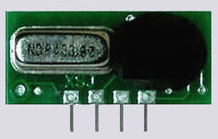
PT2262 and PT2272 must match the address codes, and the oscillation resistance must match. Generally, the decoder oscillation frequency is required to be 2.5-8 times higher than the encoder oscillation frequency, otherwise the receiving distance will become shorter or even impossible to receive. A batch of compatible chips appeared on the development market of â€. In actual use, it can be used as a complete set as long as the oscillation resistance is slightly modified. In specific applications, the external oscillating resistor can be adjusted appropriately as required. The larger the resistance, the slower the oscillation frequency, the larger the width of the code, and the longer it takes to transmit one frame. Most products on the market are combined with 2262/1.2M=2272/200K, and a few products use 2262/4.7M=2272/820K.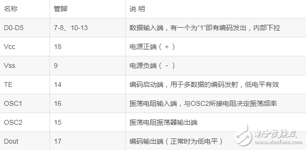


The flexible material design allows the Screen Protector to adapt to the contours of any device, so it can be connected to curved displays and rounded edges. The Full-Cover Screen Protector can perfectly fit your screen and provide maximum protection.
The oleophobic coating technology protects the glass from fingerprints left by sweat and grease, and fully supports the 3D touch function on the iPad.
Whether you are a group or an individual, we will try our best to provide you with accurate and comprehensive information about the Imported Screen Protector For iPad!