Coaxial converter principle and RF power amplifier broadband matching design detailed tutorial
In many telecommunications, radar or test systems, the transmitter power amplifier is required to operate over a very wide frequency range. For example, working on multiple octaves or even dozens of octaves. This requires broadband matching design for RF power amplifiers. Broadband power amplifiers have some significant advantages. They do not require tuning of the resonant circuit, enabling fast frequency agility or wide-bandwidth multimode signal spectrum. Broadband matching is the abbreviation of broadband impedance matching. It is the main circuit of broadband RF power amplifier and maximum power transmission system. The function of broadband matching is to achieve the best impedance matching between the input and output of the RF power amplifier tube and achieve the maximum power in the broadband. Amplify the transmission. Therefore, the design of broadband impedance matching networks is the main task of broadband RF power amplifier design. The coaxial cable impedance converter is referred to as a coaxial converter, which can achieve effective broadband matching and can provide broadband operating conditions for the RF power amplifier tube. The coaxial converter has the characteristics of large power capacity, wide frequency bandwidth and good shielding performance, and can be widely applied to the HF/VHF/UHF band.
1 program designThe coaxial converter and its combination is a wideband impedance matching network with a high impedance conversion ratio that effectively matches the lower input impedance or output impedance of the RF power amplifier tube to a standard impedance of 50 Ω. The design of the coaxial converter mostly adopts the 1:1 ratio form, the 1:4 ratio form and its combination form.
1.1 Principle of coaxial converter
The coaxial converter is composed of a length of coaxial cable or coaxial cable with a ferrite core wound around a ferrite core, and is generally called "balun". The structure of "Balun" is shown in Figure 1(a), and its equivalent circuit is shown in Figure 1(b).
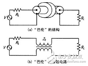
Figure 1 "Balun" structure and equivalent circuit
The coaxial converter is in the middle of concentration parameters and distribution parameters. Therefore, at the low frequency end, its equivalent circuit can be described by a conventional low frequency transformer characteristic, and at a higher frequency, it is a transmission line having a characteristic impedance of Zo. The advantage of a coaxial converter is that the parasitic inter-turn capacitance determines its characteristic impedance, while in conventional discrete turns transformers, the contribution of parasitic capacitance to frequency performance is negative.
When Rs = RL = Zo, "Balun" can be considered as a 1:1 impedance transformer. There are two points in the design and use of the coaxial converter. The source impedance, load impedance and transmission line impedance must be noted. The input and output terminals should be applied in the specified connection and grounding mode. In most cases, the cable length cannot exceed one-eighth of the minimum wavelength. In order to ensure good low frequency response, a certain winding length must also be available. The length of the required winding at the high end of the frequency and the low end of the frequency can be estimated according to the following empirical formula.
At the high frequency end:
Lmax ≤ 18 O00n/fh (cm). (1)
In the formula, fh is the highest operating frequency (MHz); n is a constant, which is generally about 0.08.
At the low end:
Lmin≥ 50Rl / [ (1 + u/uo ) &TImes; fl ]. In the formula (2), fl is the lowest operating frequency (MHz); u/uo is the relative magnetic permeability of the core at the time.
The influence of the core can be reflected by the equivalent inductance. The equivalent inductance determines the amount of reflection in the low band of the band. The calculation is:
L=uo ur n2 (S/J) (3) where L is the inductance value (H); ur is the relative permeability; uo=4πx 10-7; S is the area of ​​the magnetic ring; J is the average electrical length ;n is the number of turns of the coil.
In order to avoid the deterioration of the high-band index, the inductance value cannot be greater than the actual required value. The empirical formula is:
L = 4( R/Wmin) (4)
Where R is the input impedance of the intermediate band; Wmin is the minimum angular frequency.
1.2 1:4 coaxial converter design
The 1:4 coaxial converter consists of two coaxial cables of equal length, and its structure is shown in Figure 2(a). The 1:4 coaxial converter can be rotated horizontally by 180° as a 4:1 coaxial converter.
The input and output impedances of the ideal 1:4 coaxial converter are matched. The input and output impedance of each coaxial cable is equal to its characteristic impedance Zo. The equivalent circuit model is shown in Fig. 2(b). The transformation ratio of the load impedance ZL is: Zg / ZL = Zin / Zout = (Zo /2) / (Zo + Zo) (5)
2 and (5) show that the impedance conversion ratio of the 1:4 coaxial converter is equal to the ratio of the input impedance to the output impedance. The input impedance of the coaxial converter is equal to the parallel connection of the characteristic impedance of the coaxial cable, and the output impedance is equal to the series connection of the characteristic impedance of the coaxial cable.
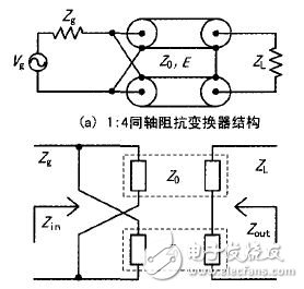
Figure 2 1:4 coaxial converter structure and equivalent circuit
1.3 Concentrated parameter component matching design
Since the characteristic impedance of the impedance converter transmission cable is a real number, the input impedance and output impedance of the RF power amplifier tube are generally complex impedances. Therefore, it is necessary to realize the input impedance and the output impedance of the RF amplifier tube to achieve conjugate matching of the source impedance or the load impedance, thereby achieving maximum power transmission. The complex impedance can be represented by a series connection of a resistor and a reactance, or by a parallel connection of a resistor and a reactance. The method of impedance matching using the lumped parameter component is that the resistance of the parallel shunt reacts to reduce the real part, and then the series reactance cancels the imaginary part to achieve matching of two pure resistors; when the matching is not pure resistance, the capacitance of the lumped parameter can be used or The inductance is used to cancel and absorb the imaginary part of the complex impedance to realize the realization of the complex impedance.
2 Key technical issues to be solved2.1 Low frequency gain suppression
The gain of the RF power amplifier decreases as the frequency increases. In general, the gain decreases by about 3 dB for each additional octave. In a narrowband circuit, the gain is reduced with increasing frequency, but in multi-octave circuits, the suppression of low frequency gain must be considered. The solution is to use a resistor negative feedback network. The resistor negative feedback network is used to suppress the high gain characteristics of the smoothing amplifier at low frequencies. The smaller the resistance value, the greater the smoothing effect. Using the high-band gain as the reference gain, use a 100-200 n resistor to reduce the gain of the low-band to 2 to 3 dB greater than the reference gain.
2.2 Coaxial cable characteristic impedance selection
The coaxial "balun" completes the balanced to unbalanced conversion, typically using a 50 n characteristic impedance. 1:4 coaxial converter cable needs to consider the source or load resistance, the formula is as follows:
Zo = (4R) 2 / 25 (Ω). (3)
Where Zo is the cable characteristic impedance; R is the source or load resistance.
2.3 Core heat dissipation and power verification
In the output matching network, when the coaxial converter transmits high power, the magnetic core will accumulate more heat due to the circuit loss, which will cause the core temperature to rise sharply. In severe cases, the magnetic permeability of the core will decrease. Affects the low frequency response of the coaxial converter. The solution is to take good heat dissipation measures for the magnetic core, and fix the magnetic core directly to the metal heat sink base with thermal conductive glue.
The choice of core material is very important. To obtain a high inductance value, a magnetic core with high magnetic permeability must be used. In order to select a suitable ferrite core for a coaxial converter, it is necessary to know the saturation magnetic flux of the core and it. Nonlinear characteristics. When the transmission power is large, the power capacity of the magnetic ring must be checked. This is due to the magnetic flux of the magnetic ring, and magnetic saturation occurs when the power is large, so that the equivalent inductance value decreases when the signal is large, and the power cannot be passed. The general rule of magnetic saturation of a coaxial converter is that the lower the frequency, the more severe it is, so its power check is performed at a low frequency.
3 design examplesAccording to the needs of the project, a multi-frequency high-power amplifier circuit is designed by using the wideband matching technology of the coaxial converter, covering the civil and military frequency bands, and the frequency range is 20-500 MHz. The power tube is a balanced n-channel enhanced RF amplifier tube BLF574 with dual-die structure. Designed for wideband power amplifiers with output power up to 350 W, power gain greater than 16 dB, and high frequency range from HF to UHF. The input and output impedances of the device are inductive at around 225MHz, the input impedance Zs = (3.2 + j2.5) Ω, and the output impedance ZL = (7.5 + j4.0) Ω.
3.1 Input Matching Network
The BLF574 has a fairly large input capacitance. In order to provide wideband matching on the multi-frequency of the input of the device, the influence of the input capacitor at the high end of the frequency must be considered, and the intermediate frequency and the lower input impedance of the lower frequency are considered. influences. The input matching network is designed as a 2-level cascading 4:1 coaxial converter, which completes the 16:1 impedance transformation and matches the 5O Ω standard impedance to approximately 3 Ω. This value is also passed through a simple series microstrip line and shunt capacitor. Converted to the input resistance of the device. The first stage 4:1 coaxial converter cable is UT-047-25, the characteristic impedance Zo=25 Ω, and the cable length is 45 mm. The core that compensates for the low frequency response is 2861002402 with an initial permeability ui = 125. The second stage 4:1 coaxial converter cable selects UT-043-l0, the characteristic impedance Zo = 10 Ω, the cable length is 45 mm, and the core that compensates for the low-frequency response also selects 2861002402. The input matching network is shown in Figure 3.
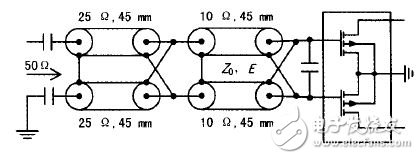
Figure 3 Input matching network
3.2 Output Matching Network
The output matching network is designed in the form of a 1:4 coaxial converter cascaded coaxial "balun". 1:4 coaxial converter cable selection UT - l4l- l5, characteristic impedance Zo = 15 Ω, cable length 68 mm. The core that compensates for the low frequency response selects 2661540202 with an initial permeability ui=125. The coaxial "balun" completes the conversion to unbalanced output, the coaxial "balun" cable is selected UT-141, the characteristic impedance Zo = 50Ω, and the cable length is 68 mm. The matching resistance is: R = (25 & TImes; 15) 1/2 / 4 = 4.8 Ω. This value needs to be converted to the output resistance of the device by a simple series microstrip line and shunt capacitor. The output matching network is shown in Figure 4.
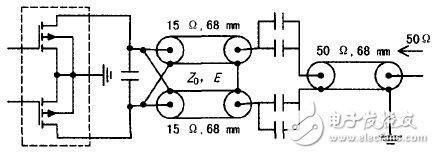
Figure 4 output matching network
3.3 Software Simulation and Test Verification
3.3.1 Software Simulation
The input impedance and output impedance of the power amplifier tube are each assumed to be variable impedance with frequency variation, and the impedance matching is performed according to the broadband network impedance approximation matching method. The software tool Ansoft-Serenade 8.7 is used to establish the coaxial impedance converter respectively. For the model's input and output broadband matching networks, the matching ports are standard 50 Ω characteristic impedances, and the matching target is the input or output port voltage standing wave ratio VSWR ≤ 2:1. Using the frequency parameter scanning curve, the length and characteristic impedance of each coaxial cable, the length of the series microstrip line and the parallel capacitance are adjusted to optimize the ideal standing wave-frequency characteristic curve in the broadband.
3.3.2 Test verification
For the actual circuit completed according to the above design, the input return loss is ≤1.95:1 in the 20-500 MHz band, and the minimum output power of the amplifier is “350 W†when the input power is 10 W. The test results show that the performance of the amplifier is good, and the designed coaxial converter matching network meets the broadband matching and power requirements.
4 ConclusionCoaxial cable impedance converter and its combination can achieve high impedance conversion ratio, and has the characteristics of large power capacity, transmission frequency bandwidth and shielding performance. Combined with a small number of centralized parameter components to form a matching network, multi-octave power amplifier is realized. Broadband matching is expected to solve the problem of a set of transmitters equipped with multiple narrowband amplifiers. The broadband matching method can be widely used in the HF/VHF/UHF band, and has good engineering application value.
Coat And Jackets ,Long Trench Coat,Sheepskin Jacket,Beige Trench Coat
GUANGZHOU LIWEI ELECTRONICS CO.,LTD , https://www.gdliwei.com