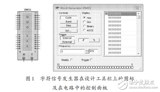
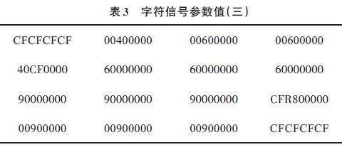
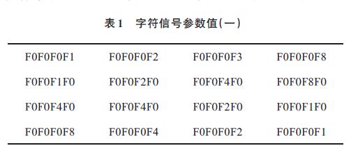
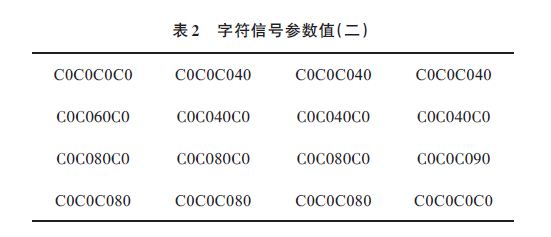
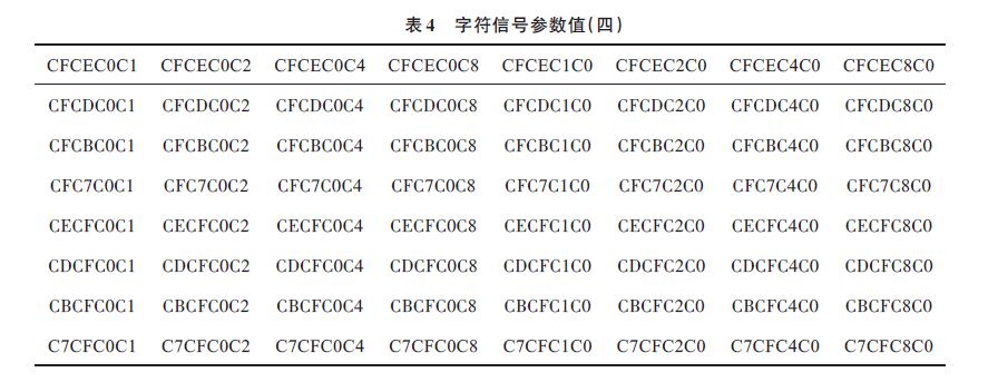
Design an 8&TImes; 8-dot LED display using MulTIsim 10 simulation software. The controller implements the design of 8&TImes;8 dot matrix LED display, which realizes progressive scroll display, column-by-column scroll display and point-by-point display. The results show that with MulTIsim 10, an efficient design platform, it is easy to design the circuit, and use the virtual instrument library to simulate and verify whether the circuit meets the design requirements. More time-saving, low cost and high efficiency compared to traditional design methods. 0 Preface The design of current digital integrated circuits is relatively modular. EDA technology refers to the computer-based work platform, which combines the latest achievements of application electronics technology, computer technology, information processing and intelligent technology to automate the design of electronic products. Using EDA tools, electronic designers can design electronic systems from concepts, algorithms, protocols, etc. A lot of work can be done by computer, and the whole process of electronic products from circuit design and performance analysis to designing IC layout or PCB layout. The automatic processing on the computer is completed. Multisim 10 is an electronic circuit design and simulation tool. In scientific research, circuit simulation tools are mainly used for circuit design and simulation. Compared with other EDA software, it has a more visual and intuitive human-computer interaction interface, especially the instrumentation in the instrumentation library is completely different from the actual instrumentation in the real experiment. The LED electronic display is composed of uniform arrangement of semiconductor light-emitting diode pixels. Different colors of LED pixels can be made with different materials. The LED display screen is brightly colored, strong in three-dimensional sense, as static as oil painting, moving like a movie, widely used in stations, terminals, airports, shopping malls, hotels, securities markets, industrial enterprise management and other public places. For example, in billboards or entertainment venues, the LED display screen is often designed to continuously change in accordance with certain rules to obtain good viewing. The following describes the Multisim 10 as the design platform to design a 8×8 LED dot matrix controller using the bidirectional universal mobile register 74LS194, LED and character signal generator to realize multiple cycles of LED display according to certain rules. 1 Color control conversion circuit design and simulation The color control conversion circuit is mainly composed of three parts: the setting of the character signal generator, the setting of the bidirectional universal shift register group and the setting of the 8×8 dot matrix LED tube. 1.1 Character signal generator settings The Word Generator is an instrument that produces 32 (bit) synchronous logic signals, also known as digital logic sources, for testing digital logic circuits. A character signal generator can send a digital or binary digital signal to a circuit to drive or test the circuit. In this circuit, the 0~7 pins of the character signal generator correspond to the first 74LS194 A, B, C, D, SL, SR, S0, S1; the 8~15 pins correspond to the second 74LS194 respectively. A, B, C, D, SL, SR, S0, S1; 16~23 pins correspond to the third 74LS194 A, B, C, D, SL, SR, S0, S1; 24~31 pins respectively Corresponding to the fourth 74LS194 A, B, C, D, SL, SR, S0, S1. Therefore, the transformation of the character signal signal is the transformation of the four 74LS194 inputs. As shown in Figure 1. 1.2 main control circuit and simulation design results The 8×8 dot matrix LED color conversion control circuit is a circuit consisting of a character signal generator, a bidirectional shift register and an LED dot matrix. Its design is shown in Figure 2. 1.2.1 74LS194 logic function and circuit design process The 74LS194 has three functions: incorporation and out, left shift, right shift. Among them, A~D is the parallel input terminal, QA~QD is the parallel output terminal, and S1 and S0 are the mode control terminals. When ~CLR is 1, when the rising edge of the clock arrives, if S1S0=11, it merges and exits, QD~ QA=D~A; if S1S0=10, left shift, QD~QA=QC~QASL; if S1S0=00, right shift, QD~QA=SRQC~QA.SR right shift serial input, SL shift left At the serial input, ~CLR is the direct unconditional clear terminal, CLR is the clock pulse input terminal, VCC is the power supply, and GND is the ground. In this circuit, the output terminals QA, QB, QC, and QD of the first 74LS194 correspond to the first row, the second row, the third row, and the fourth row of the LED matrix, respectively; the output of the second 74LS194 is QA, QB. , QC, QD correspond to the 5th row, 6th row, 7th row, 8th row of the LED matrix respectively; the output terminals QA, QB, QC, QD of the third 74LS194 correspond to the first column of the LED matrix, 2nd Column, column 3, column 4; the output of the fourth 74LS194 QA, QB, QC, QD correspond to the fifth column, the sixth column, the seventh column, the eighth column of the LED matrix. Therefore, the QA, QB, QC, and QD values ​​of the 74LS194 determine the state of the LED. 1.2.2 8×8 LED dot matrix design and working principle The 8×8 dot matrix LED display requires a total of 64 LEDs, and each LED is placed at the intersection of the row and column lines. When a corresponding row is set to a high level and a column is set to a low level, the LEDs at the intersection of the row and column lines are illuminated; if a certain row of LEDs are lit, the corresponding row is set High level, all columns are set low; if a column of LEDs is lit, all rows are set high and the corresponding column is set low. 1.2.3 Simulation Results The conversion of the lantern is mainly to realize the scroll display by controlling the parameter value of the character signal generator to control the illumination or the LED of the LED, and the result and the parameter value of the character signal generator are as follows. (1) Progressive scrolling function (scrolling order from top to bottom, then bottom to top): 1 Adopt the merge and output function to realize the progressive scroll function. The character signal parameter values ​​are as shown in Table 1, and are represented from top to bottom and left to right. 2 Use merge to merge, right shift, left shift function. The character signal parameter values ​​are as shown in Table 2. From top to bottom, the loop is represented from left to right. (2) Use the merge in, out, and right shift functions to implement the column-by-column scrolling function (the scrolling order is from left to right and then from right to left). The character signal parameter values ​​are shown in Table 3. From top to bottom, the loop is represented from left to right. (3) Use the merge and output function to realize scroll-by-point scrolling (the scrolling order is the first row, the first column, the first row, the second column, the eighth row, the eighth column). The character signal parameter values ​​are as shown in Table 4, which are represented from top to bottom and left to right. 2 Conclusion Using Multisim 10 to design and simulate each unit circuit and overall circuit of the lantern conversion control circuit, it is convenient and quick to build the circuit, and can quickly find and modify the circuit. After the circuit design simulation is completed, the actual circuit is built, thereby reducing the cost and improving the design efficiency. Electronic Components Transformer
Transformer is a device that USES the principle of electromagnetic induction to change the ac voltage. Its main components are primary coil, secondary coil and iron core.The main functions are: voltage transformation, current transformation, impedance transformation, isolation, voltage stabilization (magnetic saturation transformer), etc.According to use can be divided into: power transformer and special transformer (electric furnace change, rectifier, power frequency transformer, voltage regulator, mining, audio transformers, intermediate frequency transformer, high frequency transformer, impact transformer, instrument transformer, electronic transformer, reactor, transformer, etc.).The circuit symbol T is often used as the beginning of the number. Examples: T01, T201, etc.
Electronic Components Transformer, Electrical Transformer, AC Transformer, 12V Transformer YANGZHOU POSITIONING TECH CO., LTD. , https://www.cndingweitech.com