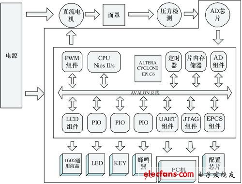
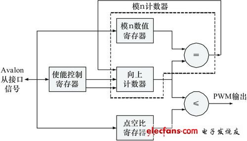
A ventilator is an instrument that can replace or assist a person's breathing function. It is suitable for artificial respiration for patients with respiratory failure or even stopping breathing. It can help patients correct hypoxia and discharge carbon dioxide, and is an important tool to save the lives of some critical patients. Most of the existing ventilator products' main control system is based on single-chip microcomputer. For products with stronger functions, high-end single-chip microcomputers are needed, which makes the cost of the system higher, more peripheral interface modules, and complicated structure. The use of SOPC (programmable system on chip) technology to design the main control system can make full use of the powerful functions of the IP core, simplify the number of peripherals, and at the same time only occupy a small part of the resources, greatly improving the cost performance of the system. This paper uses SOPC technology to design the main control system of continuous positive airway pressure ventilator. It uses Altera's Nios II soft core processor and some general-purpose IP cores. The author customizes the components based on the Avalon bus specification and controls all the logic. Integrated into a single FPGA. Medical ventilator Positive pressure ventilator uses the method of increasing the pressure in the airway to send air into the lungs. The increased pressure in the lungs expands the lung cavity. When the pressure is lost, due to the elasticity of the lung cavity tissue, the lung is restored to its original shape, and a part of the exchanged air is exhaled out of the body. At present, most ventilators use this method to increase the pressure in the airway to deliver air to the patient. The air pressure required by the ventilator is provided by a DC motor. The control signal of the DC motor is a PWM signal, and the rotation speed of the motor is controlled according to the duty cycle and period of the PWM signal. The external interface provides buttons to accept commands and set various parameters. Prompt information, status information, and parameter information are displayed on the character LCD. In order to facilitate the test of the system, UART is used as the command control interface to directly control the system, and the interface is hidden after the finished product. system structure The block diagram of the main control system of the ventilator with SOPC technology as the core is shown in Figure 1. Figure 1 Block diagram of the hardware structure of the ventilator system The core FPGA of the main control system adopts EP1C6T144C8 of Altera's Cyclone series. The CPU is the Nios II soft core processor, which manages the entire system in a unified manner. The main control board is in the broken line frame. In addition to the PC for downloading and debugging, a separate power supply is required for the DC motor and the main control board. After the DC motor is working, the airflow is sent to the mask, and the motor adjusts the airflow according to the signal at the end. The pressure detection module is installed in the mask, and it is returned to the main control board through A / D conversion for feedback adjustment of the air flow. The mask is for patients. DC motor control The system uses PWM signals to control the DC motor. There is no PWM component in the standard IP core provided by SOPC Builder, which needs to be customized. The output signal of the PWM component is a square wave, and the period and duty cycle of the square wave are adjustable. The PWM task logic structure is shown in Figure 2. Power Connectors,Circular Connector,Dc Power Jack Connector,Waterproof Dc Power Connector Shenzhen Hongyian Electronics Co., Ltd. , https://www.hongyiancon.com