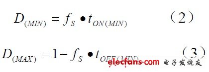
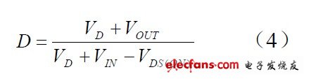
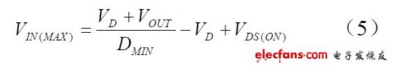
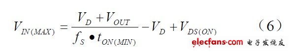
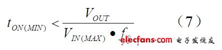
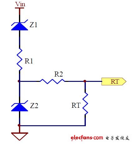
At present, high-frequency and high-efficiency DCDC converters are increasingly used in automotive electronic systems. High switching frequency can use smaller power inductance and output filter capacitor, thereby reducing the size of the system as a whole, improving the compactness of the system, and reducing the cost of the system; high working efficiency can improve the use of car batteries Time, reduce the power loss of the system, thereby reducing the calorific value of the system, optimizing the thermal design of the system, and further improving the reliability of the system. However, a high switching frequency will reduce the operating efficiency of the system, so some compromises must be made between the switching frequency and the operating efficiency during design. This article mainly discusses some design skills and precautions including the above problems when the DCDC buck converter is applied to automotive electronic systems, and these problems are often details that are easily overlooked in engineering design. 1 Actual minimum and maximum input operating voltage 1.1 Switching frequency The switching frequency must be compromised between efficiency, component size, minimum input and output voltage difference, and maximum input voltage. High switching frequency can reduce the value of inductance and capacitance, so you can use smaller size and size of inductance and capacitance, and reduce costs. However, high switching frequency will reduce efficiency and reduce the actual maximum operating input voltage, as well as require higher input and output voltage difference. The highest switching frequency can be calculated by the following formula: Where: f S (MAX) is the maximum switching frequency, tON (MIN) is the minimum on-time required by the switch, VD is the forward voltage drop of the freewheeling diode, VOUT is the output voltage, and VIN is the input for normal operation Voltage, VDS (ON) is the conduction voltage drop of the switch. The above formula shows: when t ON (MIN) is constant, a low duty cycle requires a lower switching frequency to ensure safe operation of the system. Similarly, the low switching frequency allows a lower input and output voltage difference. The main reason why the input voltage depends on the switching frequency is that the PWM controller has a minimum turn-on t ON (MIN) and a minimum turn-off time tOFF (MIN). If its value is 150ns, that is to say, the on-time of the switch tube must last at least 150ns, and if it is lower than 150ns, it may cause the MOSFET to be unable to turn on normally; similarly, the switch-off time of the switch tube should be at least 150ns, Below 150ns may cause the MOSFET to fail to turn off normally. This means that the minimum duty cycle and the maximum duty cycle are: The above formula shows that when the switching frequency decreases, the range of the duty cycle increases. The optimized switching frequency must ensure that the system has a sufficient input operating voltage range, while making the inductance and capacitance as small as possible. 1.2 Actual maximum input operating voltage Usually the input voltage of the chip has a certain rated working voltage range. In addition to the limitation of the rated working voltage, the actual input working voltage is subject to other conditions. The minimum actual input operating voltage is usually determined by the maximum duty cycle. The duty cycle of the BUCK converter is: At the highest input voltage, the duty cycle is the smallest. The maximum actual input operating voltage is determined by the minimum duty cycle of the PWM controller: If the output is under starting or short-circuit operating conditions, the input voltage must be lower than the following calculation results: It can be seen that the low switching frequency can be safely operated at a higher input voltage. The minimum on-time t ON (MIN) is the shortest duration that each controller can turn on the high-side MOSFET. It is determined by the internal timing delay and the amount of gate charge required to turn on the high-side MOSFET. Low duty cycle applications can approach this minimum on-time limit, and care should be taken to ensure: If the output voltage is in a regulated state, the system is not in a starting or short-circuit condition. If the input voltage is greater than the actual maximum allowable input operating voltage, the system can still work regardless of the operating frequency. In this situation, the duty cycle drops below the level that the minimum on-time can be adjusted, and the controller will start to enter the pulse skipping mode, that is, some pulses will be skipped to maintain the output voltage regulation. At this time, the output voltage The sum current ripple is larger than the output voltage and current ripple during normal operation. In general, when the peak detection voltage drops, the minimum on-time of each controller will gradually increase. For example, under light load conditions, the minimum on-time will gradually increase. In forced continuous operation applications with low ripple current, this This is particularly important. In this case, the duty cycle drops below the minimum on-time limit, and obvious pulse skipping occurs, and the ripple of current and voltage increases significantly. In addition, the saturation current of the inductor is usually more than 1.3 times the output current. For some severe working conditions such as starting and output short circuit and high input voltage, the saturation current of the inductor must take a larger value to ensure the safe operation of the system. Usually the switching frequency is fixed, but some synchronous buck controllers that use external resistors to set the switching frequency can add a voltage regulator Z1 and current limiting current R1 to reduce the switching frequency when the input voltage increases, thereby expanding the input voltage range, such as Figure 1. Figure 1: Frequency-reduction operating circuit at high input voltage The problem with this circuit is that at high input voltages, the output current and voltage ripple increase because the frequency decreases and the inductance is constant. The frequency changes in a wide range, the inductance cannot be optimized, and the loop compensation cannot be optimized. The minimum operating frequency of the system is set by increasing the voltage regulator Z2 and the current limiting current R2, thereby limiting the range of frequency changes.
The OREMA Marine/RV battery is an outstanding product in our range that consistently outperform traditional flooded, AGM batteries, and Gel batteries. They offer remarkable dual-purpose functionality, as they can provide both high energy for short-term starting and consistent power for longer-term cycling, making them versatile for various applications.
The OREMA Marine/RV batteries stand as a testament to innovation, providing superior dual-purpose, starting, and cycling performance compared to traditional flooded, AGM, and Gel batteries. Their resilience against a wide range of ambient temperatures, vibrations, and ability to operate in a Partial State of Charge, combined with their broad use in Marine, Caravans, Boats, and Trucks, mark them as a remarkable choice in the realm of power solutions.
Marine/RV Battery,AGM Marine/RV Battery,EFB Marine/RV Battery,Truck Battery OREMA POWER CO., LTD. , https://www.oremabattery.com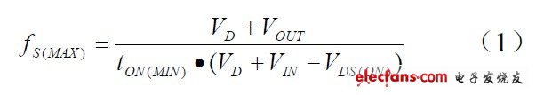
When it comes to starting performance, OREMA Marine/RV batteries excel by providing a high burst of current needed to start a vehicle's engine. This superior starting performance, even in harsh and demanding conditions, is a testament to their quality, reliability, and efficiency.
In terms of cycling performance, these batteries demonstrate exceptional ability. A battery's cycling performance refers to its capacity to go through multiple charge and discharge cycles without losing its ability to hold a charge. OREMA Marine/RV batteries, in this context, excel by retaining their capacity to hold and deliver power effectively even after numerous cycles. This superior cycling performance allows these batteries to deliver reliable power over a more extended period, making them ideal for applications that require consistent power delivery.
What sets OREMA Marine/RV batteries apart is their exceptional tolerance of a wide ambient temperature range. They remain unfazed and efficient, whether in scorching summer heat or freezing winter conditions. This temperature resilience makes them suitable for use in various climates and conditions, thereby ensuring uninterrupted and reliable performance no matter the weather.
Further bolstering their versatility and robustness is their high resistance to vibration. This is a vital feature in the boating, caravanning, and trucking world, where constant movement and bumps are part and parcel of the journey. Their vibration resistance ensures they can withstand such conditions and continue to operate optimally, making them a reliable power source in these challenging environments.
Another noteworthy feature is their capacity for Partial State of Charge (PSOC) operation. Unlike many traditional batteries that require full charging and discharging cycles, OREMA Marine/RV batteries can operate effectively even when partially charged. This flexibility means they can deliver power as needed, even if they haven't been fully charged, making them ideal for scenarios where full charging might not be possible.
OREMA Marine/RV batteries are versatile, as they are extensively used for a range of applications including Marine, Caravan, Boat, and Truck. This broad use-case potential further demonstrates their adaptability and efficiency. Their high performance in various vehicles and environments, their resilience in diverse weather conditions, and their ability to deliver power effectively irrespective of the charge level make them a superior choice for a wide range of applications.