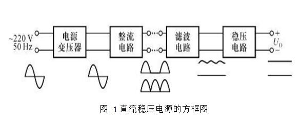
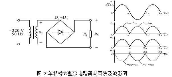
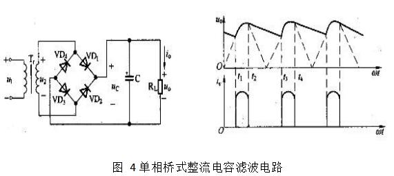
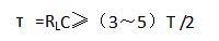
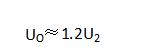
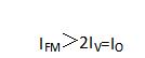
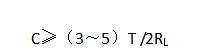
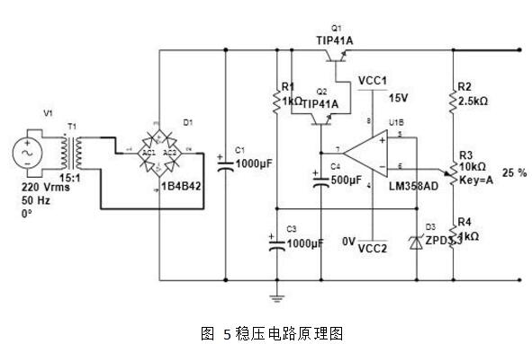
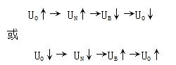
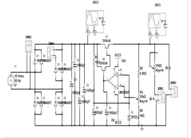
A DC regulated power supply provides an electronic device that provides a stable DC power supply to the load. The power supply of the DC stabilized power supply is mostly AC power. When the voltage or load resistance of the AC power supply changes, the DC output voltage of the regulator will remain stable. With the development of high-precision, high-stability and high-reliability of electronic equipment, DC stabilized power supply places high demands on the power supply of electronic equipment. A common feature of the linearly stabilized power supply is that its power device adjustment tube operates in the linear region and stabilizes the output by adjusting the voltage drop between the tubes. Due to the large static loss of the adjustment tube, a large heat sink needs to be installed to dissipate heat. Moreover, since the transformer works at the power frequency (50 Hz), the weight is large. The advantages of this type of power supply are high stability, small ripple, high reliability, easy to make multi-channel, and output continuously adjustable finished products. The disadvantages are large size, cumbersome and relatively inefficient. There are many kinds of stable power supplies of this kind, and the output properties can be divided into a regulated power supply and a steady current power supply, and a regulated steady current (stable) power supply that integrates regulation and steady flow. From the output value point of view, it can be divided into fixed point output power, band switch adjustment and potentiometer continuously adjustable. From the output indication, the pointer indication type and the digital display type can be divided. 1. Project Name: Linear Adjustable DC Power Supply 2, design requirements 1 output voltage: Vo = 4.5 ~ 12.0V; 2 maximum output current: Iomax ≥ 1A; 3 output ripple: VP-P ≤ 10mV; 4 voltage adjustment rate: Ku ≤ 5% (maximum output current); 5 current adjustment rate: Ki ≤ 3%. (When the output is 12V). 1, DC power supply design ideas (1) The grid supply voltage AC 220V (effective value) 50Hz, in order to obtain low-voltage DC output, the power transformer must first be used to reduce the grid voltage to obtain the required AC voltage. (2) The AC voltage after the step-down becomes a one-way pulsating DC power through the rectifier circuit, but the amplitude varies greatly (ie, the pulsation is large). (3) The pulsating DC voltage must be smoothed by the filter circuit, and the pulsation is small, so that the AC component is filtered out and the DC component is retained. (4) After the filtered DC voltage, and then stabilized by the voltage regulator circuit, a stable DC voltage output that is basically free from external influences can be obtained, and the voltage meter is supplied. 2, DC stabilized power supply principle (1) DC regulated power supply The DC stabilized power supply is a device that converts 220V power frequency AC power into a regulated DC voltage. It needs four steps of voltage transformation, rectification, filtering and voltage regulation. 1 Power transformer: It is a step-down transformer, which converts the 220V AC voltage of the power grid into a required AC voltage and sends it to the rectifier circuit. The transformer ratio is determined by the secondary voltage of the transformer. 2 rectifier circuit: using a unidirectional conductive element to convert 50Hz sinusoidal alternating current into pulsating direct current 3 Filter circuit: Most of the AC components in the output voltage of the rectifier circuit can be filtered out to obtain a relatively smooth DC voltage. 4 voltage regulator circuit: The function of the voltage regulator circuit is to stabilize the output DC voltage and not change with the AC grid voltage and load changes. (2) Rectifier circuit 1 DC circuit often uses diode single-phase full-wave rectifier circuit 2 working principle Set transformer secondary voltage u2=error! The reference source was not found. U2sinωt, U2 is a valid value. During the positive half cycle of u2, diodes D1 and D2 are turned on, and D3 and D4 are turned off. In the negative half cycle of u2, D3 and D4 are turned on, and D1 and D2 are turned off. The load resistance RL through which the current flows is inside and outside the positive and negative half cycles, and the directions are uniform. In a bridge rectifier circuit, each diode conducts electricity only for half a cycle, so the average current flowing through each diode is equal to half the average of the output current, which is the maximum reverse voltage that each diode in the circuit is subjected to. (U2 is the effective value of the secondary voltage of the transformer). (3) Filter circuit - schematic diagram of capacitor filter circuit The filter circuit can filter the AC component in the output voltage of the rectifier circuit to smooth the voltage waveform. Common filter circuits include capacitive filtering, inductive filtering, and complex filtering. At the output end of the rectifier circuit, that is, a capacitor C with a large capacitance is connected in parallel with the load resistor RL, a capacitor filter circuit is formed, as shown in the circuit of FIG. 4, because the filter capacitor is connected in parallel with the load, it is also called parallel filter. Circuit. As can be seen from Figure 3, when u2 is positive half cycle, the power supply is wrong! The reference source was not found. Power is supplied to the load RL through the turned-on diodes VD1, VD3, and simultaneously charges the capacitor C (stores the electrical energy in the capacitor, such as t1 to t2), and the output voltage U0=uc≈u2; error! The reference source was not found. After reaching the peak value, u2 decreases. When u0≥u2, VD1 and VD3 are cut off early, and capacitor C is discharged through RL. The output voltage drops slowly (such as t2~t3). Because the discharge time constant is large, the capacitor discharge speed is very slow. When uc falls not much, u2 has started the next rising cycle. When u2>u0, the power supply u2 supplies power to the load RL through the turned-on VD2 and VD4, and at the same time charges the capacitor C (such as t3~t4), so that it is repeated. After the circuit enters steady state operation, the voltage waveform of the approximate sawtooth shown by the solid line in the figure is obtained on the load. Compared with the pulsating DC (dashed line) of the rectified output, the output voltage after filtering is much smoother. Obviously, the larger the discharge time constant RLC, the smoother the output voltage. If the load is open (RL=∞), the capacitor has no discharge loop and the output voltage will remain wrong! The reference source was not found. The peak value does not change. Estimation of the output voltage: Obviously, the output voltage of the capacitor filter circuit is related to the discharge time constant τ=RLC of the capacitor, and τ should be much larger than the period T of u2. Analysis and experiments show that when The output voltage of the filter circuit can be estimated as follows, ie The rectifier diode conduction time is shortened, there is an instantaneous surge current, the diode is required to allow a larger current, and the tube parameters should be satisfied. In the case where the load resistance RL is known, the capacity of the filter capacitor C is selected according to the equation, that is, If the capacity is too small, the output voltage UO will drop. Generally, a large-capacity electrolytic capacitor is selected; the withstand voltage of the capacitor should be greater than the peak value of u2, and the factor of grid voltage fluctuation should be considered, leaving sufficient margin. The capacitive filter circuit has a poor load capacity and is only suitable for applications where the load current is small. (4) Voltage regulator circuit 1 circuit composition: the input voltage of the same operation circuit is stable voltage, and the proportional coefficient is adjustable, so the output voltage is adjustable; at the same time, in order to expand the output current, the output of the integrated operational amplifier is added with a transistor, and the emitter output form is maintained. It constitutes a series regulator circuit with an amplification section. A composite tube composed of two TIP41s is used as a regulating tube, a resistor R1 and a Zener diode D3 form a reference voltage circuit, resistors R2, R3 and R4 are sampling resistors of an output voltage, and an integrated operational amplifier LM358 is used as a comparison amplifying circuit. The adjustment tube, the reference voltage circuit, the sampling resistor, and the comparison amplifier circuit form an essential part of the series regulator circuit. Capacitors C1, C2 and C3 act as filters. 2 voltage regulation principle: for some reason (such as grid voltage fluctuation or load resistance change), the output voltage U0 is raised (lower), the sampling circuit sends this trend to the inverting input of A, and is in phase The input potential UZ is compared and amplified by the line; the output voltage of A, that is, the base potential of the adjustment tube is lowered (increased); since the circuit adopts the emitter output form, the output voltage U0 is necessarily lowered (raised), so that U0 is obtained. stable. The circuit is based on the introduction of deep voltage negative feedback to stabilize the output voltage. 3, the schematic
Absolute rotary Encoder measure actual position by generating unique digital codes or bits (instead of pulses) that represent the encoder`s actual position. Single turn absolute encoders output codes that are repeated every full revolution and do not output data to indicate how many revolutions have been made. Multi-turn absolute encoders output a unique code for each shaft position through every rotation, up to 4096 revolutions. Unlike incremental encoders, absolute encoders will retain correct position even if power fails without homing at startup.
Absolute Encoder,Through Hollow Encoder,Absolute Encoder 13 Bit,14 Bit Optical Rotary Encoder Jilin Lander Intelligent Technology Co., Ltd , https://www.jllandertech.com