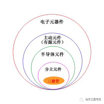
"Crystal triode is one of the basic components of semiconductors and has a current amplification function, which is the core component of electronic circuits."
In the family of electronic components, triodes are discrete components in semiconductor active components.
In a broad sense, there are many types of triodes, which are common as shown in the figure below.
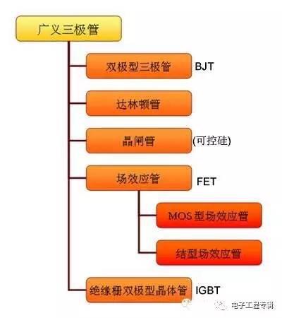
In a narrow sense, a triode refers to a bipolar transistor, which is the most basic and most common triode.
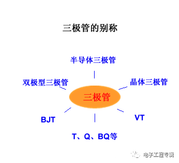
This article describes the narrow triode, which has many other names:
Triode invention
Before the appearance of the transistor, the vacuum electron transistor controls the current in the electronic circuit with amplification and switching functions.
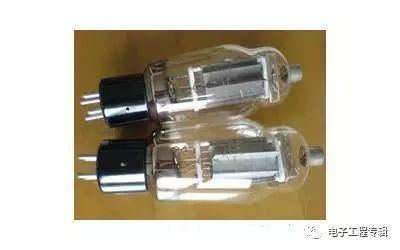
Vacuum tubes have the disadvantages of being bulky, energy intensive, and slow in response.
During World War II, the military urgently needed a stable, reliable, fast and sensitive electrical signal amplification component, and the research results were obtained after the end of World War II.
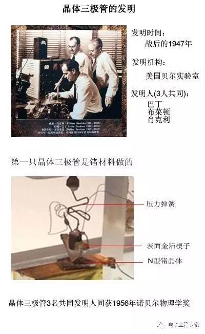
In the early days, due to the relatively easy availability of germanium crystals, the germanium transistor was mainly developed and applied. After the appearance of silicon crystals, the silicon tube was gradually eliminated due to the high efficiency of the silicon tube production process.
After half a century of development, triodes have a wide variety of shapes and shapes.
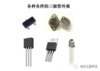
Low power triodes are generally plastic encapsulated;
High-power triodes are generally encapsulated in a metal iron shell.
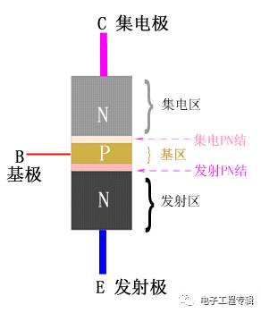
Triode core structure
The core is the "PN" knot
Are two back-to-back PN junctions
Can be an NPN combination, or a PNP combination
Since the silicon NPN type is the mainstream of the current triode, the following content mainly takes the silicon NPN type triode as an example!
Schematic diagram of NPN type triode
Silicon NPN transistor manufacturing process
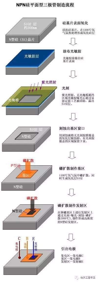
Die structure cutaway
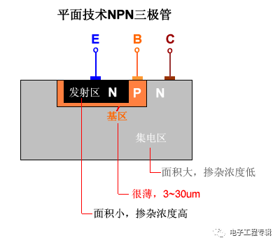
Process structure characteristics:
High doping of the emitter region: in order to facilitate emission of electrons in the emitter junction, the doping concentration of the semiconductor in the emitter region is higher than the doping concentration in the base region, and the area of ​​the emitter junction is small;
The base area is very thin: 3~30μm, and the doping concentration is low;
The collector junction area is large: the collector region and the emitter region are doped semiconductors of the same nature, but the doping concentration of the collector region is low, and the area is large, which is convenient for collecting electrons.
The triode is not a single patchwork of two PN junctions, and two diodes can't make up a triode!
The process structure is quite important in the semiconductor industry. The PN junctions can be made into a wide variety of components, including ICs, with different material compositions, sizes, arrangements, doping concentrations, and geometry.
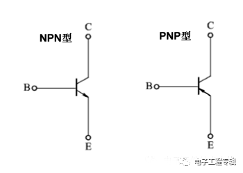
Transistor circuit symbol
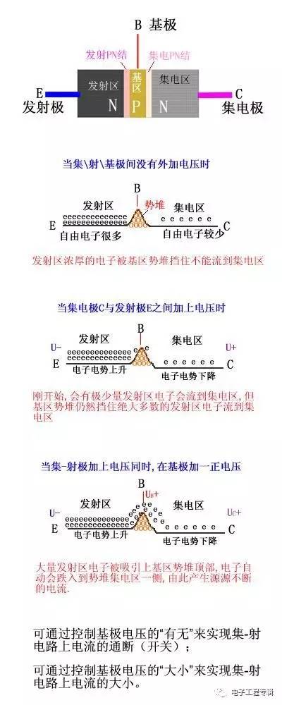
Schematic diagram of triode current control principle
Transistor basic circuit
The applied voltage forward biases the emitter junction and the collector junction is reverse biased.
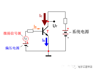
Set / base / shoot current relationship:
IE = IB + IC
IC = β * IB
If IB = 0, then IE = IC = 0
Transistor characteristic curve input characteristic curve
The relationship between the base current IB and the base-emitter voltage UBE when the collector-emitter voltage UCE is a certain value.
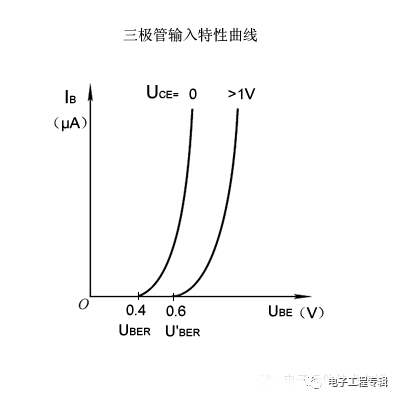
UBER is the threshold voltage of the triode starting, it will be affected by the magnitude of the collector voltage. During normal operation, the starting voltage of the NPN silicon tube is about 0.6V.
When UBEUBER, the triode will start; when the triode is high insulation, ube>
UCE increases and the characteristic curve shifts to the right, but when UCE>1.0V, the characteristic curve almost no longer moves.
Output characteristic curve
When the base current IB is constant, the relationship between the collector IC and the collector-emitter voltage UCE is a set of curves.
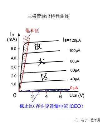
When IB=0, IC→0, called the triode is in the off state, which is equivalent to the switch being disconnected;
When IB>0, the slight change of IB will be expressed on the IC in tens or even hundreds of times;
When IB is large, the IC becomes large and cannot continue to increase with the increase of IB. The triode loses the amplification function, and the switch is turned on.
Triode core function:
Amplification function: small current changes in small currents, which are amplified at high currents.
Switch function: control the on and off of large current with a small current.
Transistor amplification
IC = β * IB (where β≈ 10~400)
Example: When the base current IB = 50μA, the collector current:
IC=βIB=120*50μA=6000μA
The weakly changing electrical signal is amplified by a triode into an electrical signal with a large amplitude, as shown in the following figure:
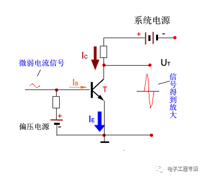
Therefore, the triode amplifies the signal amplitude, and the triode does not amplify the energy of the system. How much can you zoom in? Which one depends on the magnification of the triode beta value!
First, β is determined by the material and process structure of the triode:
For example, the commonly used range of β value of silicon triode is: 30~200
The commonly used range of beta transistor values ​​is: 30~100
The larger the value of β, the larger the leakage current, and the unstable triode performance is unstable.
Secondly, β is affected by the signal frequency and current magnitude:
The signal frequency is within a certain range, and the β value is close to a constant. When the frequency crosses a certain value, the β value is significantly reduced.
The value of β varies with the change of the collector current IC, and the value of β is small when the IC is at the mA level. Generally, the power of the small power tube is larger than that of the high power tube.
Main performance parameters of triode
There are many performance parameters of the triode, which are divided into DC, AC and limit parameters:
Types of | Parameter item | symbol | significance |
DC parameter | Common beam DC amplification factor | β | No alternating signal input, the ratio of the common current of the common-emitter circuit. β=IC/IB |
Co-based DC amplification factor | α | No alternating signal input, the ratio of the common base circuit collector. |
Set-shot Reverse current | ICEO | The base is open, and the reverse current between the collector and the emitter is also called leakage current and penetration current. |
Collector Reverse current | ICBO | Collective junction reverse current (leakage current) when the emitter is open ICEO=βICBO |
AC parameter | Common beam AC amplification factor | β | Common-emitter circuit, set base current change ratio: β = ΔIC / ΔIB |
Co-base AC amplification factor | α | Common base circuit, ratio of collector current variation: α = ΔIC / ΔIE |
Common beam cutoff frequency | Ƒβ | β due to the frequency increase 3dB corresponding frequency |
Common base cutoff frequency | Ƒα | α decreases by 3dB due to the increase in frequency |
Characteristic frequency | ƒT | The frequency increases and β decreases to the corresponding frequency. |
Limit parameter | Collector maximum current | ICM | The maximum current allowed by the collector. |
Collector maximum power | PCM | If the actual power is too large, the triode will burn out. |
Set-emitter breakdown voltage | UCEO | When the base is open, the collector-emitter withstand voltage value. |
Effect of temperature on triode performance
The temperature affects almost all of the parameters of the triode, with the greatest impact on the following three parameters.
(1) Effect on magnification β:
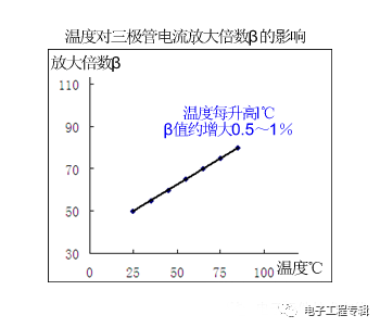
When the base input current IB does not change, the collector current IC increases sharply due to temperature rise.
(2) Effect on reverse saturation current (leakage current) ICEO:
ICEO is formed by minority carrier drift motion, which has a large relationship with ambient temperature, and ICEO increases sharply with temperature. When the temperature rises by 10 ° C, ICEO will double.
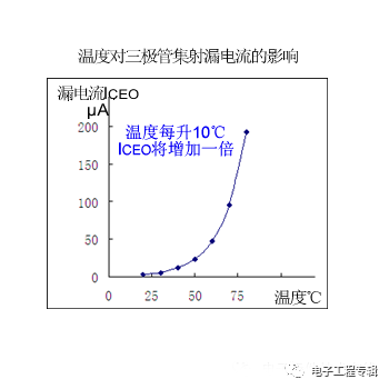
Although the leakage current ICHO of the silicon tube is small at normal temperature, the leakage current will be as high as several hundred microamperes or more after the temperature rises.
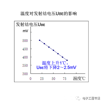
(3) Effect on the emitter junction voltage UBE:
When the temperature rises by 1 °C, the UBE will drop by about 2.2 mV.
As the temperature rises, β and IC will increase, and UCE will decrease. In the circuit design, appropriate measures should be taken, such as away from heat sources, heat dissipation, etc., to overcome the influence of temperature on the performance of the triode.
Classification of triodes
Classification angle | species | Description |
From technical processes | By material | Silicon Transistor 0.6V é”—Triode 0.3V | normally: The fistula is PNP type Silicon tube is NPN type |
By structure | PNP type NPN type |
By manufacturing process | Flat type Alloy type Diffusion type | High frequency tube is mostly diffused Low frequency tube is mostly alloy type |
From performance | By frequency | Low frequency tube <3MHz Medium frequency tube 3~30 (MHZ) High frequency tube 30~500 (MHZ) UHF tube >500MHZ |
By power | Low power PCM <0.5W Medium power 0.5 High power PCM >1w | The larger the power, the larger the volume, and the higher the heat dissipation requirement. |
Features use | Amplifying tube High back pressure tube With damper tube | |
From package outline | According to packaging materials | Metal package glass package Ceramic package plastic package Thin film package | Plastic packaging is the mainstream Metal packaging costs are higher |
In package form | Leaded TO SMD SOT | The patch type is gradually replacing the lead type. |
Triode naming
Different countries have different names for triode models. There are also many manufacturers using their own naming methods.
Chinese mainland triode naming method
3 | D | D | 12 | X |
2: Diode 3: Triode | A: PNPé”— B: NPNé”— C: PNP silicon D: NPN silicon | X: low frequency and low power G: high frequency and low power D: low frequency and high power A: high frequency and high power | Serial number | Specification number |
Example: 3DD12X NPN type low frequency high power silicon triode
Japanese triode model naming method
2 | S | D | 13 | B |
0: Photocell 1: diode 2: Triode | Registration mark | A: PNP high frequency tube B: PNP low frequency tube C: NPN high frequency tube D: NPN low frequency tube | Electronic association registration order | Improved model |
Example: 2SC1895 high frequency NPN type triode
American Electronics Industry Association (EIA) triode naming
JANS | 2 | N | 2904 | A |
JANTX: Special-level JANTXV: Super Special JANS: Aerospace (none): non-military supplies | 1: diode 2: Triode "n": n PN junction components | EIA registration mark | EIA registration sequence number | Different grades |
Example: JANS2N2904 Aerospace Triode
European triode naming
B | C | 208 | A |
A: fistula B: Silicon tube | C: low frequency and low power D: low frequency and high power F: high frequency and low power L: high frequency and high power | Registration sequence number | Beta file |
Example: BC208A silicon material low frequency small power triode
Transistor package and pin arrangement About package:
The higher the rated power of the triode design, the larger its volume, and due to the continuous development of packaging technology, the triode has a variety of package forms.
Currently, plastic packaging is the mainstream packaging form of triodes, with "TO" and "SOT" form packages being the most common.
About the pin arrangement:
The definitions of the triode pins of different brands and different packages are not exactly the same. Generally, there are the above rules:
Rule 1: For the medium-high power triode, the collector is obviously thicker or even connected by a large-area metal electrode, and is mostly between the base and the emitter;
Rule 2: For the patch transistor, when facing the mark, the left is the base, the right is the emitter, and the collector is on the other side;
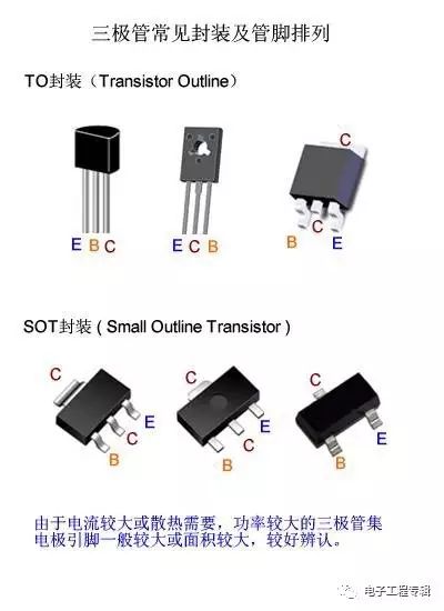
Base - B Collector - C Emitter - E
Principle of selection of triode
Consider the performance limits of the triode and select the appropriate performance parameters according to the “2/3†safety principle. :
Collector Current IC:
IC < 2 / 3 * ICM
ICM collector maximum allowable current
When IC>ICM, the beta value of the triode is reduced, and the amplification function is lost.
Collector power PW:
PW < 2 / 3 * PCM
The maximum allowable power of the PCM collector.
When the PW> PCM transistor will burn out.
Set-shot reverse voltage UCE:
UCE < 2 / 3 * UBVCEO
Set-shot reverse breakdown voltage when UBVCEO is open
When the collector/emitter voltage UCE>UBVCEO, the triode generates a large collector current breakdown, causing permanent damage.
Working frequencyÆ’:
Æ’ = 15% * Æ’T
ƒT — characteristic frequency
As the operating frequency increases, the amplification capability of the triode will decrease, and the frequency ƒT corresponding to β=1 is called the characteristic frequency of the triode.
In addition, the volume cost should also be considered, and the patch transistor is preferred.
Sewage Gas Generator,Propane Powered Generator,Hydrogen Generator,Gasoline Generator