ST's STNRG011 is a multi-mode PFC controller that includes a high-voltage dual-ended controller for LLC resonant half-bridges, an 800V starting voltage generator, and a digital engine that optimally manages three blocks. It is mainly used in open switching power supplies (SMPS). ), Flat TV switching power supply, ATX power supply and AC / DC adapter. This article describes the STNRG011 main features, block diagram and detailed block diagram, typical application circuit diagram and based on STNRG011 and SRK2001 12V/150W power supply evaluation board EVLSTNRG011-150 main characteristics and indicators, Circuit diagrams and bill of materials.
Draw-wire sensors of the wire sensor series measure with high linearity across the entire measuring range and are used for distance and position measurements of 100mm up to 20,000mm. Draw-wire sensors from LANDER are ideal for integration and subsequent assembly in serial OEM applications, e.g., in medical devices, lifts, conveyors and automotive engineering.
Linear Encoder,Digital Linear Encoder,Draw Wire Sensor,1500Mm Linear Encoder Jilin Lander Intelligent Technology Co., Ltd , https://www.jilinlandermotor.com
The STNRG011 embodies a mulTI-mode (transiTIon-mode and DCM) PFC controller, a highvoltage double-ended controller for the LLC resonant half-bridge, an 800 V-rated startup generator and a sophisTIcated digital engine, that manage opTImal operation of three Blocks.
The device comes in a 20-pin SO package and offers an advanced solution for power factor-corrected high-efficiency converters supposed to comply with the most stringent energy saving regulations.
The power system and the control algorithms are managed by an 8-bit core with dedicated fast peripherals (SMED). Optimized digital algorithms together with HW analog IPs are implemented to guarantee a very high performance, BOM optimization and robustness.
The digital algorithms are stored into an internal ROM memory and all key application
Parameters can be stored into a device's NVM (non-volatile memory) memory during the
Production phase suspect wide configurability and calibration.
The device can also externally communicate through a 2-pin UART, allowing the monitoring function, the black box storing into an external E2PROM and the software patch upload from the external E2PROM.
STNRG011 main features:
Digital combo multi-mode PFC + time-shift LLC resonant half-bridge controller
Onboard 800 V startup circuit, line sense and X-cap discharge compliant with IEC 62368-1, for reduced standby power
Enhanced fixed on time multi-mode TM PFC controller with input voltage feedforward, THD optimizer and frequency limitation
Complete set of PFC protections
Time-shift control of resonant half-bridge
Enhanced burst-mode at light load with fast ransient response and line adaptive halfbridge brown-out protection
Complete set of half-bridge protections
Available in SO20 package
STNRG011 Application:
Open frame SMPS
Flat screen TV SMPS
ATX power supply
AC-DC adapter 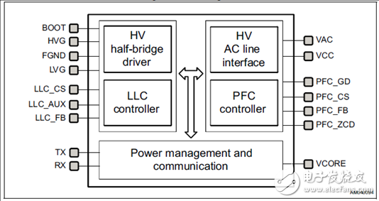
Figure 1. STNRG01 block diagram 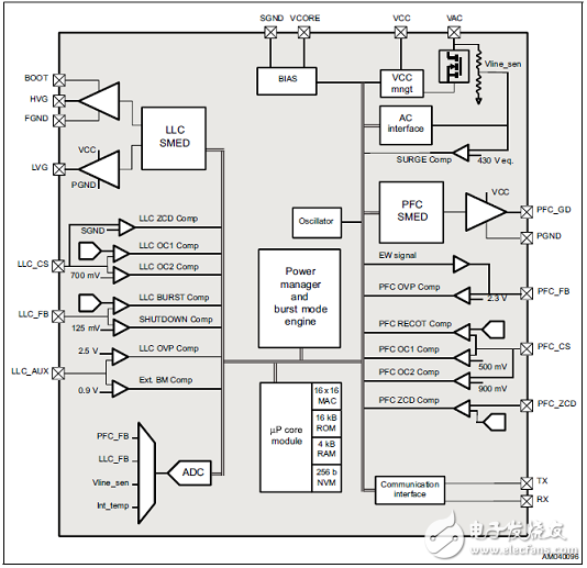
Figure 2. Detailed block diagram of STNRG011 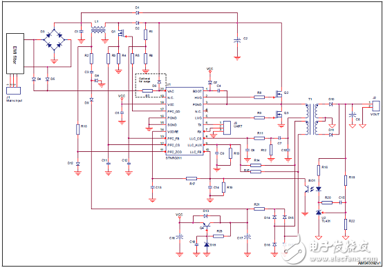
Figure 3. Typical Application Circuit of STNRG011
12V/150W Power Supply Evaluation Board EVLSTNRG011-150 Based on STNRG011 and SRK2001
The EVLSTNRG011-150 is a 12 V, 150 W power supply demonstration board for 90 V ac to 264 V ac mains, which is representative of an AC/DC converter for an all in one (AIO) computer or a general purpose high power adapter .
The design is based on the STNRG011 IC, a digital combo that controls a two-stage AC/DC SMPL. The front-end is a transition mode PFC pre-regulator and the second stage is an LLC HB resonant converter. The SRK2001 implements the Synchronous rectification in order to obtain higher efficiency.
No auxiliary supply is needed due to the very low consumption at no load.A full set of auxiliary functions and protection is also provided, this allows reduction of the overall BOM while maintaining a rugged design.
The performances of the EVLSTNRG011-150 can meet the requirements of major standards ENERGY STAR® for computers ver. 6.1, EuP Lot 6 Tier 2, European CoC ver. 5 Tier-2, in terms of efficiency, no-load input power and power Factor and feature harmonics content well below the limits of European Standard EN61000-3-2 Class-D and Japanese standard JEITA-MITI Class-D regulations.
Evaluation board EVLSTNRG011-150 main features:
Digital controller: STNRG011
TM PFC with resonant HB-LLC converter
Input voltage range: 90  264 V ac
12 V ± 5% CV output regulation
Full-load power: 150 W continuous operation
Peak power loading: 200 W
Full-load and average efficiency: greater than 90% at 115/230 V ac
Peak efficiency: greater than 93%
No-load mains consumption: less than 75 mW
Hold-up time: greater than 10 ms
Full set of programmable parameters
High degrees of flexibility thanks to the configurable NVM
Black box functionality with the installed EEPROM 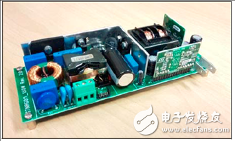
Figure 4. Evaluation Board EVLSTNRG011-150 Outline Drawing Evaluation Board EVLSTNRG011-150 Main Specifications: 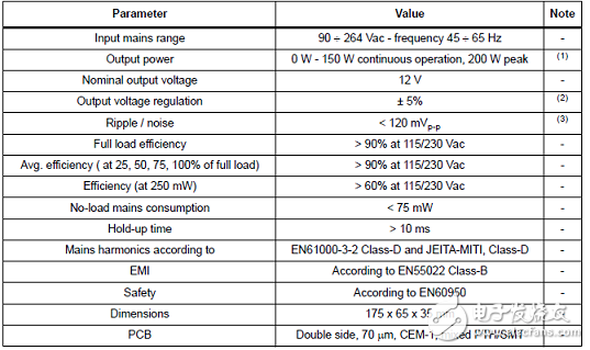
![[SOLVED] ST STNRG011 Multi-Mode PFC Controller Solution](http://i.bosscdn.com/blog/20/21/01/45U_0.png)
Figure 5. Block Diagram of the EVLSTNRG011-150 Evaluation Board 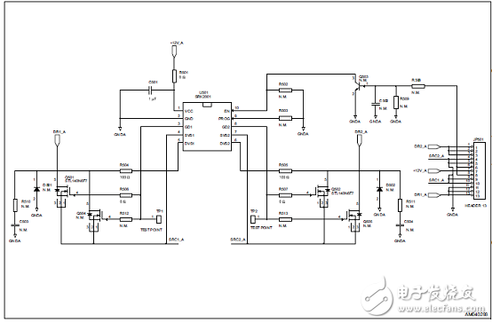
Figure 6. Control loop reference circuit diagram 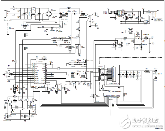
Figure 7. Evaluation board EVLSTNRG011-150 circuit diagram: motherboard circuit
Figure 8. Evaluation board EVLSTNRG011-150 circuit diagram: feedback (control) board circuit 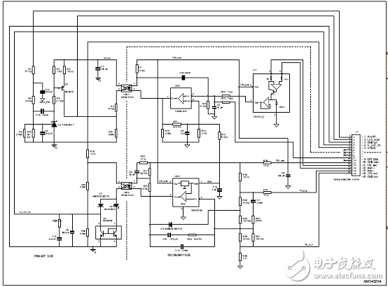
Figure 9. Evaluation Board EVLSTNRG011-150 Circuit Diagram: Synchronous Rectification (SRK) Board Circuit Evaluation Board EVLSTNRG011-150 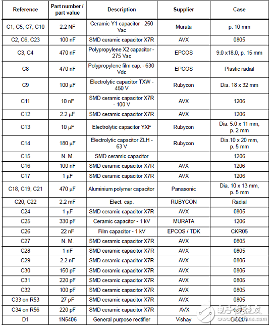
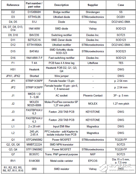
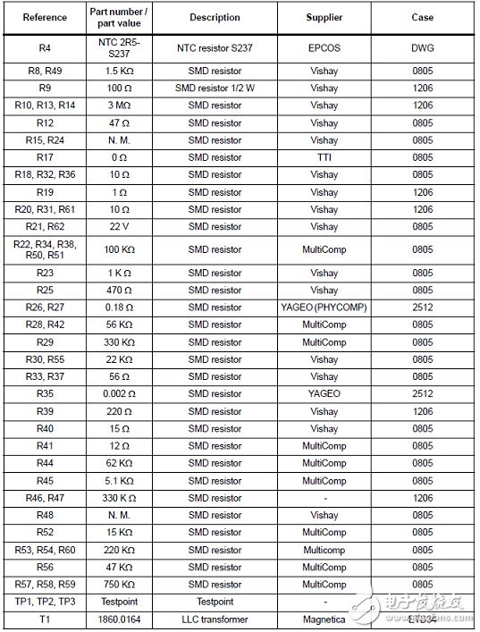
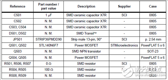
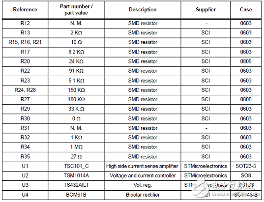
Evaluation Board EVLSTNRG011-150 Feedback (Control) Board Material List: 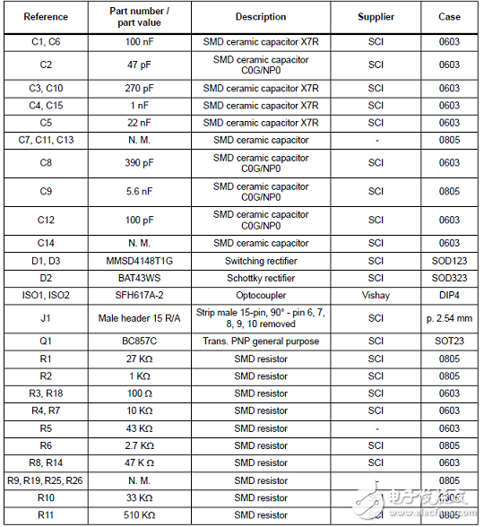
Evaluation board EVLSTNRG011-150 synchronous rectification (SRK) board material list: