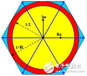
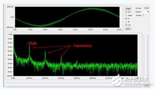
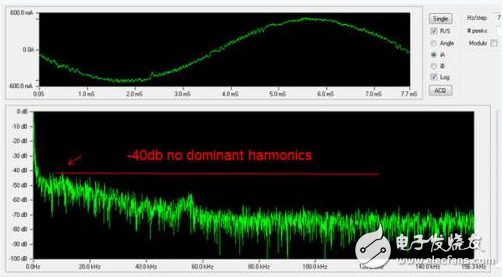
Environmental protection has always been a topic of concern. In order to achieve a low-carbon life, governments in developed countries use taxes and fees to reduce carbon emissions and energy use. More than half of the electricity is used to drive the motor, so designers should not have to use more efficient motor control and design. This article will introduce the use of magnetic field orientation control (FOC) algorithm and pulse frequency modulation (PFM) to closely control the motor to achieve high precision and high efficiency. Scalar control (or commonly referred to as voltage/frequency control) is a simple control method that changes the torque and speed of the motor by changing the power supply (voltage) and the frequency supplied to the stator. This method is quite simple and can be done even with an 8/16-bit microprocessor. However, the simple design is accompanied by the biggest drawback - the lack of robust and reliable control. This control method is sufficient if the load is kept constant at high speeds. But once the load changes, the system can't respond quickly, resulting in energy loss. In contrast, FOC provides tight motor control. This method is designed to maintain the stator current and magnetic field in an orthogonal state (ie, at a 90 degree angle) to achieve maximum torque. Since the magnetic field-related information obtained by the system is constant (whether obtained from the encoder or estimated in sensorless operation), it can accurately control the stator current to achieve maximum mechanical torque. In general, FOC is more complex and requires 32-bit processor and hardware acceleration. The reason is that this method requires several computationally intensive modules, such as Clark transform, Parker transform, etc., to perform mutual conversion between three-dimensional or two-dimensional coordinate systems to extract the relationship between current and magnetic flux. As shown in Figure 1, the inputs to be considered for controlling the motor include the target torque command, supply current, and rotor angle. The conversion and calculation are done based on these parameters, and the new drive value of the power electronics is calculated. The time required to complete a cycle of FOC is called the loop time. As expected, the shorter the loop time, the faster the system will respond. A fast-responding system means that the motor can quickly adjust to the load and compensate for errors in a shorter period of time for smoother motor operation and higher efficiency. Figure 1: Field Oriented Control tightly controls motor torque and improves efficiency. The shorter the loop time, the faster the system responds. The FOC algorithm is typically implemented using an embedded processor with loop times between 50us and 100us, depending on the model and available hardware. In addition, software can be used to implement FOC, but its certainty cannot be guaranteed. Therefore, a large number of designs rely on FPGA hardware acceleration to take advantage of the determinism and high-speed processing of this technology. Using the most advanced 28nm FPGA technology, the typical FOC current loop time is 1.6us1, which is significantly shorter than the software approach. Since enhanced motor control not only reduces noise, but also improves efficiency and accuracy, most current loops are currently implemented in hardware and tend to migrate speed loops and position loops into hardware implementations. This approach is possible because with the advancement of digital electronic circuit technology, a single device has enough computing power. The speed control loop time and position control loop time implemented by FPGA are 3.6us1 and 18us1, respectively. This is a significant performance improvement over traditional software approaches because traditional location loop times are typically in the millisecond range. Modulation is also a key module for improving energy efficiency. Different modulation schemes can be used depending on the load, performance requirements and application requirements, and these modulation schemes have a significant impact on the operation of the motor control system. The modulation schematic (Figure 2) analyzes several modulation schemes we are going to review in this article. The most basic modulation scheme uses a six-step modulation method, which represents six possible combinations of three-phase power bridges (excluding the 111 and 000 null states, in which all switches are turned off). This switching method is represented as six blue vertices of a hexagon. The six-step modulation method applies the maximum power to the motor, that is, the output voltage of the inverter is equal to Vdc. Although the output power is large and the design implementation is simple, if the motor requires high precision and high robustness, the six-step modulation method should not be used. This is because the motor runs in a non-linear state and needs to "jump" from one state (vertex) to another state and cannot run smoothly. For smoother operation of the motor, sinusoidal modulation can be used. Can the sinusoidal modulation method make the motor run smoothly? Although this method is slightly more complicated than the six-step modulation method, and there is no advantage in efficiency, because the output of the inverter is only half of Vdc, basically Vdc/ 2 = 0.5 Vdc. On the modulation schematic, this is represented as the inner circle of the red circle. Figure 2: Modulation schematic To compensate for the losses caused by sinusoidal modulation, space vector PWM (SVPWM) modulation is derived. The SVPWM can provide a voltage of 1/√3Vdc=0.5773Vdc. Similar to sinusoidal modulation, SVPWM also allows the motor to run smoothly. On the modulation schematic, this is represented as the outer circle of the red circle. Figure 3 is a waveform comparison of the sinusoidal modulation method and the SVPWM modulation method. Figure 3: Waveform comparison of sinusoidal modulation and SVPWM modulation Both sinusoidal modulation and space vector modulation use pulse width modulation (PWM), one of the most common industrial modulation techniques. However, pulse width modulation uses a fixed modulation frequency to adjust the control of the supply voltage by changing the pulse width, so the occurrence of harmonics is a problem. Harmonics are the cause of EMI, motor vibration, and energy loss. To suppress harmonics, another modulation method can be used, namely using pulse frequency modulation (PFM). Pulse frequency modulation allows a small number of pulses to be held at a fixed width and modulated at different periods (frequency) depending on the desired value. This modulation method reduces harmonics because the harmonics are spread across all frequencies. Figures 4 and 5 show the comparison of the FFT (Fast Fourier Transform) frequency analysis of PWM and PFM. It can be clearly seen that the PFM can eliminate the third harmonic distortion. Figure 4: Harmonics generated by a pulse width modulation scheme. Harmonics can cause energy loss and motor vibration. Figure 5: Harmonics generated in a pulse frequency modulation scheme can be spread across all spectrums. No harmonic peaks are visible. Resistance furnace transformer
The resistance furnace transformer and salt bath furnace transformer with small capacity and low voltage are mostly dry-type transformers, with a box shell and natural cooling; Resistance furnace transformers with medium capacity (hundreds to thousands of volt amperes) are mostly oil immersed self cooling transformers; Large capacity is forced oil circulating water-cooled transformer.
furnace transformer for ladle,resistance furnace transformers,electric furnace transformer,induction furnace transformers, arc furnace transformers Henan New Electric Power Co.,Ltd. , https://www.newelectricpower.com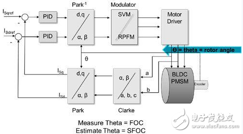

Electric resistance furnace and salt bath furnace for heating, heat treatment of mechanical parts, powder metallurgy sintering, non-ferrous metal smelting, etc. Because the resistance of the heater is too small, or the resistance of the heater changes too much during the heating process, a resistance furnace transformer needs to be equipped between the furnace and the power grid to reduce and adjust the input voltage of the furnace.
A special transformer used to supply power to electric arc furnaces for iron and steel smelting. Large capacity, complex structure and high technical requirements. Its secondary side voltage is low, generally from tens of volts to hundreds of volts, and it is required to be adjustable in a large range; The secondary side current often reaches thousands to tens of thousands of amperes. In addition, in iron and steel smelting, large power is required during the melting period, and the transformer is required to have 20% overload capacity within 2 hours. In the process of steelmaking, electrode short circuit is easily caused by the collapse of furnace charge, so the primary side of the electric arc furnace transformer should be connected to the current limiting reactor in series or have a large impedance to limit the short circuit current.
Special transformer for intermediate frequency furnace
The special transformer for medium frequency furnace produced by the company is applicable to medium frequency electric furnace below 30 tons. The rated voltage at the primary side can be divided into 10KV or 35KV. The rated voltage of the secondary side can be divided into: 400V, 600V, 660V, 690V, 700V, 720V, 750V, 800V, 850V, 900V, 950V, 1000V, 1050V, 1100V, 1250V, etc. Rectification mode can be divided into 6 pulse, 12 pulse, 24 pulse or more. The current popular rectifier string, inverter string, rectifier parallel, etc