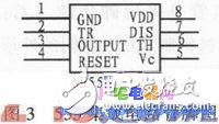
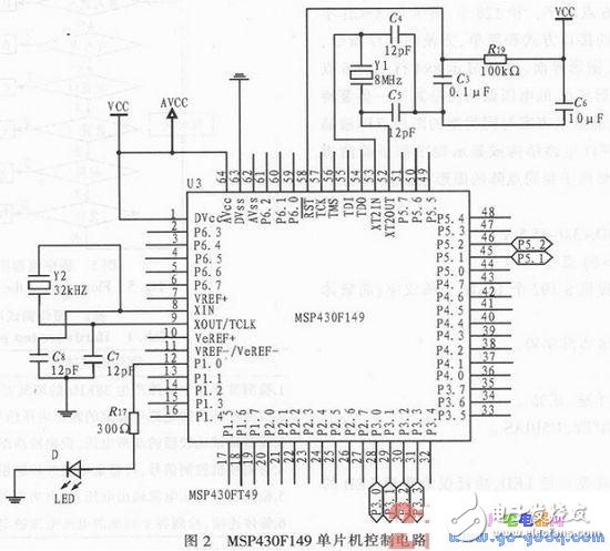
The article mainly describes the design of a personnel registration and entry system using video image analysis technology. The signals of people entering and leaving the library are collected by infrared rays and sent to the single-chip MSP430F149. The single-chip computer processes the statistics and enters the hall, and displays the number of people on the LCD12864 LCD screen. At the same time, the people entering and leaving the library are photographed. And store. Through the personnel registration and entry system, the accurate number of people and photos in the library can be obtained in time, which is beneficial to the museum's more efficient organization. It can be integrated with third-party software systems to provide data support for scientific decision-making. The personnel registration and entry system is designed for the exhibition hall. The system is mainly composed of five parts: single chip control, signal acquisition, photographing, liquid crystal display and power supply. The hardware structure is shown in Figure 1. When someone wants to enter the hall, the signal collected by the infrared device will be sent to the MCU, the MCU will process the collected signal, and control the camera to take pictures of the person entering the hall, and record the time of admission, then on the LCD screen. The number of people in the hall is displayed. When someone goes out of the hall, the working principle of this system is the same as that of the hall. The functions that the system can achieve are: 1) Display the number of people in the hall; 2) Take photos of people entering and leaving the library; 3) When the hall is full, there is a clear sign and it is forbidden to enter; 4) Record the time people enter and leave the museum. The MSP430 series MCU is used as the control chip, and the signal acquisition circuit uses the infrared integrated tube as the main component. The camera is used for photographing, the LCD12864 liquid crystal display is used for the display part, and the self-made +5 V regulated power supply is used for the power supply part. Compared with the 51 series MCU, the MSP430 MCU has strong processing capability, convenient peripheral circuits and reset function. It is a new-generation single-chip microcomputer with high speed/low power consumption and super anti-interference. Its interrupt, timing, and I/O output are far more than the 51 series, and the internal integrated comparison amplifier and multi-channel AD determine that it is very strong. The scalability, so the system uses MSP430F149 microcontroller as the control chip. Compared with pressure sensors, infrared sensors are non-contact sensors, which have much smaller losses than pressure sensors. They have the advantages of fast reflection speed, long service life and easy maintenance and inspection. So in this environment we choose to use an infrared sensor. 2.1 MCU control module MSP430 is a newly developed DSP with FLASH with 16-bit bus. It uses 16-bit bus, peripheral and memory addressable, addressing range up to 64K, and can be expanded beyond the memory. Interrupt management, with rich on-chip peripheral modules, on-chip precision hardware multiplier, two 16-bit timers, a 14-channel 12-bit analog-to-digital converter, a watchdog, 6-channel P-port, two-way USART Communication port, a comparator, an internal oscillator and two external clocks, support 8M clock, because it is FLASH type, the MCU can be debugged and downloaded online, and the JTAG port is directly connected to the FET, no additional The simulation tool is convenient and practical. Moreover, it can work in ultra-low power mode, and the radiation to the environment and the human body is small. Therefore, the system uses the MSP430F149 microcontroller as the control chip. MSP430F149 microcontroller control circuit shown in Figure 2. 2.2 Infrared sensing and communication module Infrared light emitting diode Infrared light emitting diode is made of semiconductor materials such as gallium arsenide (GaAs) and gallium arsenide (GaAlAs). Their shapes are basically the same as ordinary light emitting diodes. Resin material package. Medium and high power infrared light-emitting diodes use a metal or ceramic material as the base and a glass or resin lens as the window. 2.3 Waveform Generation Module The 555 integrated circuit is initially used as a timer, so it is called a 555 timer or a 555 time base circuit. It can also be used for dimming, temperature regulation, voltage regulation, speed regulation and other various control and measurement detection, forming pulse oscillation, monostable, bistable and pulse modulation circuits for AC signal source, power conversion, frequency conversion, pulse Modulation, etc. It is reliable, easy to use, and inexpensive, and is currently used in a variety of electronic products. We used a 555 integrated circuit to generate a square wave of 38 kHz. The 555 integrated circuit is an 8-pin package with dual in-line type, as shown in Figure 3. The 6-pin is called the threshold terminal (TH), which is the input of the upper comparator. The 2-pin is called the trigger terminal (TR), which is the lower comparator. Input; 3 pin is the output (Vo), it has 0 and 1 states, which is determined by the level applied by the input terminal; 7 pin is the discharge end (DIS), which is the output of the internal discharge tube, which is suspended. The two states are also determined by the state of the input; the 4 pin is the reset terminal (MR), and the output is low when the low level is applied; the 5 pin is the control voltage terminal (Vc), which can be used to change the up and down trigger. Level value; 8 feet are the power supply end, and 1 pin is the ground end. 2.4 Photo Camera Module The system uses a high-definition video head, which can be connected to a PC. It has a visual monitoring interface and can control the video head through hardware. The time is automatically saved and printed when taking a photo. 2.5 LCD module Molded Waterproofing Cable Assemblies We specialize in waterproofing products overmolding. We can custom build, custom mold, and over-mold your cable designs.
We specialize in molded cable manufacturing for the widest diversity of
cable and connector types, across the whole spectrum of industries. Rich expeirence in developing and proposing solution Special for IP67, IP68 waterproofing products. Molded waterproofing cable assemblies, waterproof wire harness, waterproofing cables overmolding ETOP WIREHARNESS LIMITED , https://www.oemwireharness.com
The demographic system can play different roles in different applications. It can obtain information such as the number of people in the mall and the flow direction of the crowd in the mall or retail outlets, which is useful for assessing the attractiveness of the products to customers and assessing whether the location of the mall is appropriate; for large buildings, managers can use The population statistics system understands the behavior of the crowd and assesses whether the facilities provided by the building are convenient and sufficient, such as seats, public telephones and sanitation facilities, to improve the utilization of building facilities, to guide the design of buildings and to improve the staff of certain occasions. Efficiency, in addition, can monitor the flow of passengers in the building to avoid the safety hazards caused by crowd congestion. 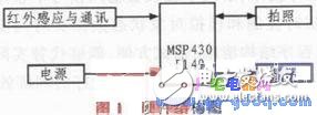
Infrared Receiver Diode The infrared receiving tube of the receiving circuit is a kind of photodiode. When used, the infrared receiving diode should be reverse biased for normal operation to obtain high sensitivity. Infrared receiving diodes are generally available in both circular and square shapes. Since the transmitting power of the infrared light emitting diode is small, the signal received by the infrared receiving diode is weak, so the receiving end is required to increase the high gain amplifying circuit.
Infrared remote control communication module Considering that the system may be installed in a higher place, ordinary wired buttons cannot meet the actual requirements. Therefore, we chose to use the infrared remote control button to control the system.
The infrared remote control button human-computer interaction module includes two parts: the hardware infrared receiving transistor receiving part and the single-chip software decoding.
The transmitting portion is a fixed frequency wave and a binary number (high and low level) modulation to be transmitted is transmitted in the form of light through an infrared transmitting tube.
The receiving part decodes and modulates the modulated signal into a transmitted binary number (high and low level) through an infrared receiving transistor, and achieves multi-button remote control by a specific programming of the single chip microcomputer.