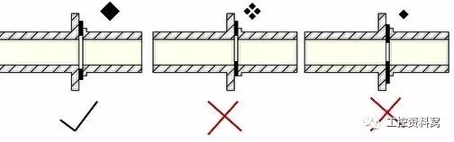
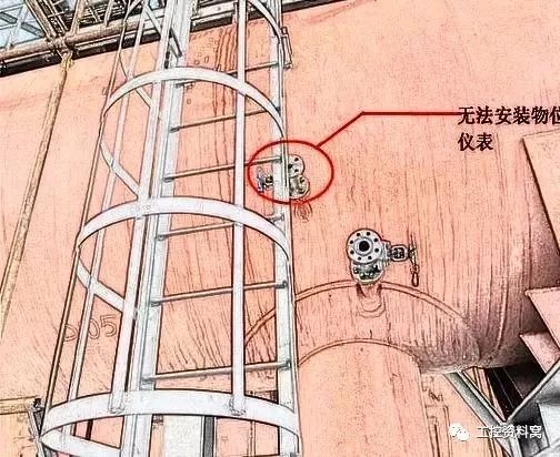
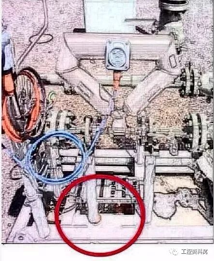
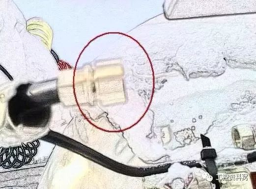
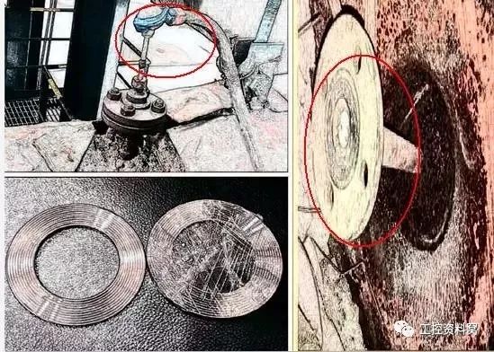
If any measuring instrument fails, it will cause trouble to the entire production process, and even cause interruption of the production process or cause safety problems. So, how can the huge production system be effectively maintained to avoid the failure of the instrument control system? Common minor problems with meters 1. The flow signal of the vortex flowmeter is unstable. Check on site. Are the gaskets concentric during installation? The result is to reinstall. 2. The level meter in the picture is taken from the source part, it can be clearly seen that this meter cannot be installed. 3. The mass flow meter is installed, the pipeline is not in the middle, and reinstall it. 4. The core wire connected to the level gauge is bent, causing the core wire to be short-circuited with the outer wall of the connector, and the display shows +E. If the core wire is not connected to the connector, the display shows -E or 000L. 5. Reasons for errors during temperature measurement: 1) Improper installation causes errors. The depth of thermocouple insertion should meet the requirements. The thermocouple and power cable should not be installed in the same conduit to avoid introducing interference and causing errors. 2) Insulation deterioration introduces errors. Poor insulation between the poles and defects of the thermocouple will cause the loss of thermoelectric potential and introduce interference, thereby causing errors. 77 common pits, enter with caution... 1. Do not mix the signal cable and the power supply cable with a multi-core cable! 2. Do not stick oil in the maintenance of oxygen pipeline instrument equipment, and do not mix oil-free transmitters and pressure gauges with ordinary meters. 3. When repairing the instrument and removing the wires, you must pay attention to wrap the wire ends to prevent short circuits! 4. The cable should not have an intermediate joint. 5. Point shield grounding, generally shield grounding at the control room side. 6. The protective hose must be lower than the meter inlet to prevent water from entering the meter. 7. The leaky instrument should be equipped with an instrument protection box or wrapped in nylon plastic bag. 8. When cables are laid in the trough (public account: pump housekeeper), the intrinsically safe cables, power cables, and signal cables should be separated by partitions. 9. When wiring, the compensation wire can not use the lug (sheet) to avoid contact between two different conductors and cause measurement errors. 10. During production, if the instrument needs to deal with problems, including indoor and outdoor, it must be handled in accordance with the procedures or regulations, especially the operator must be notified, and sometimes a written signature is required. 11. In areas with lightning protection, the field instruments are connected to the safety barrier after the surge protector and then connected to the DCS, SIS and other control systems. In order to avoid redundant wiring between the cabinets, the surge protector and the corresponding circuit in the cabinet room are safe Install the grid on the same side as possible in the cabinet. 12. The control room must take measures to prevent small animals, because the mouse peeing on the ESD card causes the entire device to stop, and the loss can be described as large. 13. The unit debugging must be completed before the instrument is installed, and the loop debugging must be completed after the installation is completed before joint debugging. 14. When the device is running, the technician must be present for the maintenance of the instrument. Keep in mind that if something goes wrong, it is no small matter. 15. For on-site maintenance of the instrument, you must contact the technologists, and ask about the process status. When disassembling the instrument with power, you must turn off the power first, and then use a multimeter to confirm whether the power is off. You must know that life is yours. 16. When designing a flow meter, be sure to select an appropriate flow meter type according to the measuring medium, temperature, and pressure, and do a good job of flow compensation. Attention should be paid to various special requirements of flow meters during installation. 17. When the instrument is designed into the slot plate of the control room, in order to prevent rainwater from entering the control room, it must be bent up and down and sealed. 18. When the instrument air is introduced from the main pipe, the valve must be above the center of the pipeline, preferably at a position 90 degrees above the pipeline, to avoid stolen goods in the wind line: entering the instrument valve. 19. The shielding layer must not be grounded at both ends; the outdoor cable protection nozzle should have rainproof measures; the explosion-proof environment should pay attention to the sealing of the nozzle. 20. The alarm equipment and audio equipment must be well maintained and put into use normally, otherwise, if there is an accident in the process, the professional instrument will have to peel off. The reason is that the alarm is broken and the operator has not found it. 21. For the occasions involving ammonia, copper and copper alloys are prohibited; for DCS system power supply, dual power supply should be designed to enter! 22. Thermal resistance temperature measurement, long-distance transmission cannot use two-wire system. 23. The insulation resistance of the cable should be greater than 5 megohms; the turning radius of the cable should generally be greater than 10 times the diameter of the cable, and 15 times the optical cable; the instrument cable should be laid parallel to the electrical cable at a certain distance (more than 0.8 meters), and the distance between the equipment and pipeline The spacing is greater than 150 mm. 24. Instrument pipeline hydraulic test. When testing austenitic stainless steel pipelines, the chloride ion content in the water must not exceed 25PPM (parts per million). The instrument grounding should be less than 1 ohm, and the other grounding should be less than 4 ohms. 25. The protection of meters should be fireproof cloth "asbestos cloth". Plastic bags should not be used. 26. The instrument used in the hydrogen unit must meet the requirements of explosion-proof level and protection level, and none of them are indispensable. Intrinsically safe signals (cables) and flameproof signals (cables) cannot enter the same site intermediate junction box. 27. The insulation resistance of the cable should be greater than 5 megohms; the turning radius of the cable should generally be greater than 10 times the cable diameter, and 15 times the optical cable; the instrument cable and the electrical cable should be laid in parallel with a certain distance (more than 0.8 meters), and the distance between the equipment and the pipeline The spacing is greater than 150 mm. 28. Instrument pipeline hydraulic test. For austenitic stainless steel pipelines, the chloride ion content in the water must not exceed 25PPM (parts per million). The grounding of the instrument should be less than 1 ohm, and the other grounding should be less than 4 ohms. 29. The instrument used in the hydrogen unit must meet the requirements of explosion-proof level and protection level, and none of them are indispensable. Intrinsically safe signals (cables) and flameproof signals (cables) cannot enter the same site intermediate junction box. 30. When designing the FF bus, it is necessary to install a terminator (resistor and capacitor connected in series) at the terminals of the power supply regulator and the field bus junction box. 31. The solenoid valve used for interlocking should be of fail-safe type, which is energized under normal conditions and cut off during interlocking. 32. When designing and installing the instrument, if the pipeline installed with the temperature instrument is below DN80, use a thermometer expansion tube to expand the pipeline to above 80. 33. The flow measuring element does not participate in the power plant hydraulic test. 34. Measure steam flow. When condensers are used in the positive and negative pressure guiding pipelines, the installation height of the two condensing tanks should be kept the same. 35. The simmering system of the pressure guiding tube of the field instrument uses cold simmering, and cannot use hot simmering such as gas welding. 36. The occurrence of flashing must be fully considered in the process of designing and selecting control valves, designing pipelines, and determining pressure distribution. From the perspective of the control valve, the following items should be noted. Improve the hardness of the material. Reduce the flow rate of the fluid. Choose the appropriate control valve type and flow direction. For example, for fluids that are easy to vaporize, it is not appropriate to use high pressure recovery balls. 37. For valves and butterfly valves, single-seat valves with low pressure recovery can be used. Measures to eliminate and reduce what actually happened: Control the pressure drop so that cavitation does not occur. For example, a multi-stage pressure reduction method is used to divide the pressure drop of the control valve into several stages. Reduce the influence of cavitation. Use similar methods to prevent flash evaporation. For example, increase the hardness of the material, reduce the flow rate, etc., to reduce the impact of cavitation. Reasonably distribute pipeline pressure and increase downstream pressure. 38. Problems that should be paid attention to when laying cables and wires overhead into the control room: Before entering the control room, give the trough a fixed fulcrum to prevent climate change and stress on the indoor equipment; Before the trough plate enters the control room, there must be a slope of more than 1/100, slope to the outside, to prevent rainwater from flowing into the control room along the trough plate; Entrance and exit through the wall of the control room should be sealed to prevent rats and mosquitoes from entering. 39. The choice of local pressure gauge must clearly distinguish the nature of the pressure source: whether it is an impact load or a general pressure. There are not many meters at that time, and replacement can be miserable. The installation size of the in-situ thermometer must be communicated with the process, and the size must be selected when measuring the liquid that is not full of the tube; the material selection of high temperature and high pressure must be different from that of normal temperature and pressure during design. Do not dismantle and construct equipment with electricity, and carry test pencils to prevent the risk of electric shock. 40. Do not dismantle and construct equipment with electricity, and carry test pencils to prevent the risk of electric shock. 41. DCS must do a good job of anti-static work, do not cause accidents due to static electricity. 42. To check and repair chain equipment, DCS must be forced to act. 43. The solenoid valve coil must not be unplugged when it is energized, otherwise it will burn out the coil. 44. When the rotor and wheel flowmeter are installed vertically, be sure to pay attention to the fluid from bottom to top. 45. After the newly installed regulating valve, the air supply pipeline should be vented for a period of time before connecting to the valve positioner to prevent oil from entering and causing damage to the positioner. 46. ​​The acetylene gas instrument should also be banned from copper, so in addition to the explosion-proof requirements when using acetylene gas, it should also be noted that the nameplate of some devices will be marked "not suitable for acetylene gas". 48. For the steam tracing of the instrument pipeline, the heat tracing pipe should be above 12O.D., otherwise, once the route is long, the steam is not hot and the heating effect is not good. 49. To correct a mistake that is easy to make in a design, no matter what kind of anti-riot system the system is, some people add safety barriers uniformly. In fact, safety barriers are used in intrinsically safe explosion-proof systems. Intrinsically safe explosion-proof system: Field instruments must be intrinsically safe instruments; There must be a safety barrier on the side of the control room. The cable in the middle must be an intrinsically safe signal cable. 50. For increased safety instruments and explosion-proof instruments, if necessary, an isolator can be used for signal isolation. 51. Zener type safety barrier must pay attention to the grounding problem. 52. In fact, the instrument and the process are inseparable. On-line maintenance of the instrument must pay attention to minimize the interference to the process. 53. Selection of flow meters: When the conductivity of the measured process medium is low, electromagnetic flowmeters cannot be used; for measurements with high factory-level measurement requirements, mass flowmeters should be used. 54. When measuring the pressure of the medium, when the temperature of the measured medium is greater than 60 degrees, a condenser or siphon should be added. 55. After installing the pneumatic control valve, be sure not to reverse the setting of the air-opening and air-closed functions on the DCS. 56. The indicated value of the temperature instrument system suddenly changes to the maximum or minimum, which is generally a failure of the instrument system. Because the measurement lag of the temperature instrument system is large, no sudden changes will occur. At this time, the fault causes are mostly caused by thermocouple, thermal resistance, compensating wire disconnection or transmitter amplifier failure. 57. Be sure to mark the wire number when wiring the instrument! I have made such a low-level mistake in my work at the beginning, and it is troublesome to recover. If the primary part is installed at the bend of the pipeline or installed at an angle, it should be against the flow direction. 58. If there is a pressure point or a temperature point on the same pipeline at the same time, the pressure point should be upstream of the temperature point. 59. The rotameter must be installed vertically on the pipeline, and the flow direction of the medium must be from bottom to top. 60. Straight pipeline requires 5DN on the upstream side and 3DN on the downstream side (DN is the diameter of the pipeline). 61. When installing the electromagnetic flowmeter, pay attention to the positive and negative direction or arrow direction of the flowmeter should be consistent with the flow direction of the medium. 63. The minimum straight pipe section is 5DN on the upstream side and 2DN on the downstream side. 64. The arrow of the regulating valve must be consistent with the flow direction of the medium. Angular pressure regulating valve for high pressure drop, the flow direction is along the bottom of the spool into and out. 65. When installing a small-diameter regulating valve with threaded connection, a removable connection must be installed. 66. The regulating valve should be installed firmly. Large-size control valves must be supported. The operating handwheel should be in a position that is convenient for operation. 67. The condensate discharge of the instrument heating system must be designed reasonably, and use traps as little as possible, which is easy to block. 68. It is strictly forbidden to touch it with your hands before the meter has not stopped rotating or before the device under test is discharged. Do not touch the metal part of the lead when removing the wire. During the telemetry, no one can work on the device under test. 69. (1) The power line and the signal line must be separated, and the same cable cannot be used to prevent interference; (2) The shielding layer must not be grounded at both ends, otherwise an electrical difference will be formed; (3) The cable should not have intermediate joints; (4) 220V power supply and 24V power supply should be separated; (5) Power ground and signal ground (PLC) ground must be separated; (6) Compensation issues must be considered for flow measurement... 70. When using radar level timing, you must check the dielectric constant of the medium, whether it is too low, otherwise you cannot use the radar level gauge. When using guided wave radar, the material of the wave guide (rod) meets the anti-corrosion requirements. When using the horn-mouth radar, pay attention to the installation requirements and not too close to the wall, otherwise there will be false echoes. 71. The disassembly and inspection of the instrument valve must be carried out after the process is processed and confirmed, otherwise the consequences are at your own risk; the inspection and repair of the interlocking instrument must be released after the relevant ticket; the disassembly of the single (double) flange instrument must be slow Remove the bolts slowly to prevent splashing and hurting people. When selecting the instrument flange, you must pay attention to the sealing surface, pressure level, material and standard to prevent the wrong type. 72. The radar level gauge is especially suitable for products with high pollution or high viscosity, such as asphalt. The repeatability of the radar level gauge measurement is high, without regular maintenance and recalibration, and the measurement accuracy is also high, but the price is high, and it is difficult to measure the oil-water interface. 73. Isolation type transmitter is mainly used for special measured medium. For example, the measured medium will crystallize after leaving the equipment, while the ordinary type transmitter needs to take out the medium, which will block the pressure guiding tube and bellows chamber. It cannot work normally, so the isolation type must be selected. The isolation type is usually installed as a flange type, that is, a flange is added to the device under test so that after the transmitter is installed, its sensing diaphragm is a part of the device wall, so that it will not take out the measured medium and generally will not cause crystal blockage . When the measured medium requires a high crystallization temperature, a structure that protrudes the diaphragm can be selected, so that the sensing diaphragm can be inserted into the device, so that the temperature of the sensed medium will not decrease, so the measurement is guaranteed. That is, the plug-in flange transmitter is selected. 74. The main basis for the selection of pressure/differential pressure transmitter: Take the property index of the measured medium as the standard, and take the reference to saving money, easy installation and maintenance. If the measured medium is high-viscosity, easy to crystallize and strong corrosion, an isolated transmitter must be selected. 75. When selecting the type, consider the corrosion of its medium to the metal of the bellows. The material of the bellows must be selected, otherwise the outer diaphragm will be corroded in a short time after use, and the flange will also be corroded to cause damage to the equipment. And personal accidents, so the choice of material is very important. The diaphragm of the transmitter is made of ordinary stainless steel, 304 stainless steel, 316L stainless steel, tantalum diaphragm, etc. 76. The temperature of the measured medium should be considered when selecting the model. If the temperature is generally 200°C~400°C, the high temperature type should be selected, otherwise the silicone oil will vaporize and expand, making the measurement inaccurate. 77. The working pressure level of the equipment should be considered when selecting the model. The pressure level of the transmitter must be consistent with the application. From an economic point of view, the outer membrane box and the insert part are made of suitable materials, but the connecting flange can be made of carbon steel and chrome plating, which will save a lot of money.
Semiconductor Chip Carrier can be divided into thermo-electric modules, and the power electronic substrates.
Thermo-electric modules are plate-like semiconductor cooling devices that work by using the movement of heat when a current flows through the junction of two different metals. Compact, lightweight, and Freon-free, they are used in climate control seats of automobiles, cooling chillers, optical communications, biotechnology, air conditionners, dryers and a variety of consumer electronic products.
Application of Thermo-electric module Manufacturing Technology for Heat Dissipation and Insulation Substrate
Generally, organic and metal substrates are used in the circuit boards of low-power home appliances and computers.
In particular, silicon nitride substrates are attracting attention for use in power modules of inverters and converters because of the increase in sales of HEVs and EVs. Chip Carrier Package,Ceramic Chip Carrier,Plastic Leaded Chip Carrier,Chip Carrier Socket SHAOXING HUALI ELECTRONICS CO., LTD. , https://www.cnsxhuali.com
However, alumina, aluminum nitride and silicon nitride substrates are used in heat radiation insulated substrates of power modules that handle high power.