Is the MEMS Inertial Measurement Unit (IMU) used in the self-balancing guidance system of the personal vehicle platform, whether there will be a consumer-oriented, can eliminate all alignment errors between the sensors, and all core sensor components are integrated in a single chip On the IMU? No, for this design, this is generally not an insurance expectation. Industrial-grade IMUs with robust discrete sensors and optimal packaging and optimized calibration have much higher alignment accuracy than consumer-grade IMUs on a single chip. Consumer and industrial IMUs often specify shaft alignment characteristics in different ways. A typical practice for consumer IMUs is to aggregate all alignment errors into one cross-axis sensitivity specification. Industrial-oriented IMUs, such as the ADIS16490, use two different specifications to more directly account for alignment accuracy: axis-to-axis alignment error and axis-to-package alignment error. The shaft-to-package alignment error describes how well each axis is aligned relative to the mechanical properties within the IMU package. Axis-to-axis alignment error describes how well the alignment of each accelerometer and gyroscope axis fits the ideal orthogonality. For this reason, the axis-to-axis alignment error is often referred to as quadrature error. Cross-axis sensitivity (CAS) and axis-to-axis alignment error (A2A_MAE) have the following mathematical relationships: CAS = sin(A2A_MAE) A2A_MAE = asin(CAS) Non-orthogonality occurs between the sensor shafts, on the sensor, or from the misalignment of the package between the sensor and the housing. For industrial-grade IMUs, these specifications are factory calibrated and detailed in the data sheet. For discrete devices, the cross-axis sensitivity specification does not include assembly deviations relative to the PCB. Ideally, multiple axes in the gyroscope and accelerometer are orthogonal to each other. However, there is a common misconception: Since the multi-axis accelerometer or gyroscope may be designed in a discrete within the MEMS device, it should be perfectly orthogonal axes, a 90 ° angle to each other. Although all of the inertial sensors in these devices are located on a single chip, the inherent errors introduced by processing and manufacturing variations can still cause quadrature errors. The corresponding equivalent alignment accuracy is actually not very good compared to a fully calibrated industrial grade IMU. Figure 1. The ideal triaxial orthogonality on the left reflects the true effect of the vector. The quadrature error allows for partial rotation or force of the leak to be detected on all axes. A simple survey of consumer devices found that cross-axis sensitivity is often in the range of 1% to 5%. Using the above relationship, it can be seen that the equivalent axis-to-axis alignment error is 0.57° to 2.87°. However, it can also be defined in milliradians, which is equivalent to 0.057°. Industrial-grade IMUs are usually much more accurate. We can also use this relationship to convert the industrial-grade IMU's axis-to-axis alignment error of 0.018° to an equivalent cross-axis sensitivity of 0.031%. CAS = sin(A2A_MAE) = sin(0.018°) = 0.00031 = 0.031% All of the inertial sensors of the industrial-grade IMU ADIS16489 are not located on a single chip. Despite this obvious drawback, their performance is still about 32 times higher than that of the best consumer-grade devices. To understand the effect of quadrature error, assume that an accelerometer axis points directly above and the device is just in a horizontal state. The accelerometer measures the total effect of gravity on this z-axis. If the other two axes are completely orthogonal, they will not measure any gravity vector. However, if there is a quadrature error, the other two horizontal axes will measure a part of the gravity vector. For example, if the device's cross-axis sensitivity is 1%, its equivalent response to gravity will be 10 mg, which is equivalent to an equivalent alignment error of 0.6°. Conversely, if the first axis is not orthogonal to the horizontal frame, it will not detect the full gravity vector. Quadrature error is a particularly stable component of the total accelerometer error and can therefore be corrected by a one-time calibration. To determine the quadrature error of a pair of accelerometer axes, the accelerometer must be rotated in all possible 90° directional spaces and the static response of each axis to gravity should be measured. This can be done with a precision gimbal head or on a known orthogonal surface. After mounting the device to the PCB, it is difficult to eliminate the quadrature error under all operating conditions by calibration. Inertial calibration requires observing the response of each sensor while the device is undergoing a controlled motion pattern. In order to efficiently implement such sports modes, highly specialized equipment and experience are often required. Unlike pre-calibrated industrial-grade IMUs, every consumer-grade MEMS device mounted on a PCB needs to be calibrated for other sensors, environmental performance, and temperature. After the discrete devices are mounted in rugged modules on the micro PCB, the industrial-grade IMU, which includes three gyroscope axes and three accelerometer axes, utilizes calibration steps to achieve superior performance in manufacturing. This factory calibration not only identifies and compensates for the quadrature error of the MEMS device itself, but also compensates for assembly-related skew. Therefore, errors related to assembly deviation, cross-axis error, and temperature are minimized. ADIS16489 factory calibration minimizes shaft alignment errors in platform stabilization, navigation and robotic applications. The ADIS16489 includes a digital three-axis gyroscope and a three-axis accelerometer with a gyroscope axis-to-axis alignment error of only ±0.018° and an accelerometer axis-to-axis error of ±0.035°. In addition to high-performance sensor parameters, the ADIS16489 utilizes a parylene coating as a moisture barrier for internal circuitry.
Copper Cooling Tube
[HIGH REFRIGERATION EFFICIENCY]Good heat dissipation and refrigeration capability,high strength at low temperature.Copper tubes are hollow,so has strong heat transfer capability.If you need refrigeration for refrigerators, freezers, air conditioners, this is a good choice
Condenser Copper Tube,Copper Cooling Tube,Copper Tube Air Cooling,Copper Cooling Fin Tube FOSHAN SHUNDE JUNSHENG ELECTRICAL APPLIANCES CO.,LTD. , https://www.junshengcondenser.com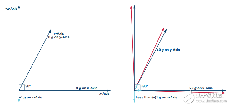

[SOFT & SHAPE CHANGEABLE]Because refrigeration copper pipe can bend and deform, they can often be made into elbows and joints. Smooth bending allows copper tubes to bend at any angle
[WIDELY APPLICATION]Refrigerator Tubing is not only used for refrigerator, freezer and air conditioner as refrigeration tubing coil, but also used as a HVAC system pipe.