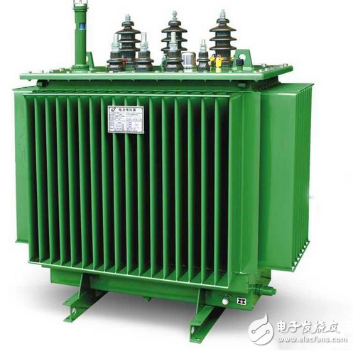
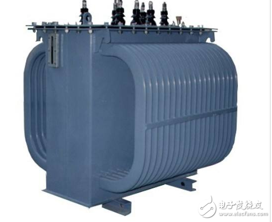
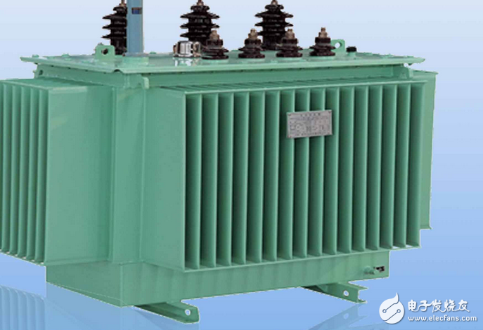
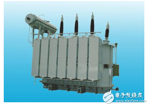
Rectifier diodes are mainly used in rectifier circuits, so the fault mechanism of rectifier circuits is related to rectifier diodes. A set of methods for detecting diodes can be used for troubleshooting faults. Regarding the failure mechanism of the rectifier circuit, the following points are mainly explained: 1. The root cause of the failure of the rectifier circuit has two aspects: one is the destructive influence of the external circuit on the rectifier diode, which is not the fault of the rectifier circuit itself; the other is the quality problem of the rectifier diode itself, due to the comparison of the operating current of the rectifier diode Large, prone to failure. 2. The rectifier diode has two hard faults, open circuit and breakdown. Its soft fault is the increase of the forward resistance of the diode and the decrease of the reverse resistance, and the working stability is poor. 3. After the forward resistance of the rectifier diode increases, the voltage drop across the rectifier diode increases, and the DC voltage applied to the load resistance of the rectifier circuit decreases, reducing the DC output voltage of the power supply circuit. The larger the rectified DC operating current is, the larger the tube voltage drop on the rectifier diode is, and the rectifier diode itself is also hot. In severe cases, the rectifier diode will be burned out. 4. After the reverse resistance of the rectifier diode is reduced, the unidirectional conduction performance of the diode is deteriorated, so that a part of the other half of the alternating voltage is applied to the load resistance of the rectifier circuit through the rectifier diode, because this is an alternating voltage, so it is increased. The ripple voltage in the DC operating voltage increases the burden on the filter circuit. Regarding the key test points of the rectifier circuit, the following points are mainly explained: 1. The key test point of the rectifier circuit is the output end of the rectifier diode. The DC voltage of the multimeter can be used to measure the DC voltage of the output terminal of the rectifier diode. When there is DC voltage output, the rectifier circuit can work normally. Otherwise, the rectifier is rectified. The circuit may be faulty. 2. In the positive rectifier circuit, the negative pole of the rectifier diode is the output terminal of the rectifier circuit, and the positive DC voltage is measured at this time; in the negative rectifier circuit, the anode of the rectifier diode is the output terminal of the rectifier circuit. The negative DC voltage is measured. The effective detection means for the failure of the rectifier circuit mainly describes the following points: 1. After the power is cut off, measure the forward and reverse resistance of the rectifier diode in the road. It can be judged whether the diode is open or short. If the measurement result cannot be determined, the rectifier diode can be disconnected from the circuit and measured. The test results are accurate. 2. Measure the DC voltage drop between the two pins of the rectifier diode under power-on state. Under normal conditions, the silicon rectifier diode is 0.6V, and the 锗 rectifier diode is 0.2V. This is true for any polarity rectifier circuit. 3. For the soft fault of the diode, it can be verified by replacing a new rectifier diode. After the replacement, the fault disappears, indicating that the judgment is correct, otherwise the possibility of the rectifier diode failing is also ruled out. The rectifier transformer rectifier transformer is the power transformer of the rectifier equipment. The rectification device is characterized by the original input current, and the secondary side outputs DC after rectifying the original. Converter is a general term for three working modes of rectification, countercurrent and frequency conversion. Rectification is one of the most widely used. A transformer used as a power source for a rectifying device is called a rectifying transformer. Most of the industrial rectified DC power supplies are obtained by the AC grid through rectifier transformers and rectifier equipment. 1. Is the appropriate voltage to supply the rectification system, 2. It is to reduce the pollution of the power grid caused by the waveform distortion caused by the rectification system. The rectifier transformer is the power transformer of the rectifier device. The rectification device is characterized by the original input AC, and the secondary side outputs DC after rectifying the original. Converter is a general term for three working modes of rectification, countercurrent and frequency conversion. Rectification is one of the most widely used. A transformer used as a power source for a rectifying device is called a rectifying transformer. Most of the industrial rectified DC power supplies are obtained by the AC grid through rectifier transformers and rectifier equipment. This is the industry that applies the most rectification, electrolyzing non-ferrous compounds to produce aluminum, magnesium, copper and other metals; electrolyzing salt to make chlor-alkali; electrolyzing water to produce hydrogen and oxygen. DC grid for mines or urban electric locomotives. Due to the empty line of the valve side connector, the short circuit fault is more, the DC load changes the amplitude, and the motor car often starts, causing different degrees of short-term overload. For this reason, the temperature rise limit and current density of such transformers are both low. The impedance is about 30% larger than the corresponding power transformer. Mainly used to power DC motors in electric drives, such as the armature and excitation of rolling mills. (4) The voltage of such a rectifier transformer for direct current transmission is generally above 110 kV, and the capacity is tens of thousands of kilovolt-amperes. Special attention should be paid to the problem of intersection and DC superposition of ground insulation. In addition, there are DC power supplies for electroplating or electromachining, DC power supplies for excitation, and DC power supplies for charging and electrostatic precipitators. In the chemical industry with the most rectification, the high-power rectifiers also have low secondary voltages and large currents. Therefore, they are similar to electric furnaces in many respects, that is, the structural features mentioned above, and the rectifier transformers are also available. The biggest characteristic of the rectifier transformer is that the secondary current is not sinusoidal. Because of the single-conduction characteristics of the subsequent rectifying components, the phase lines are no longer at the same time, the load current is flowing but the soft current is conductive, and the unidirectional pulsating current is changed by the filtering device. For direct current, the secondary voltage of the rectifier transformer, the current is not only related to the capacity connection group, such as the commonly used three-phase bridge rectifier circuit, the double-reverse balance circuit with the balanced reactor, for the same DC output voltage and current required. The secondary voltage and current of the rectifier transformer are different. Therefore, the parameter calculation of the rectifier transformer is based on the rectification circuit. The general parameter calculation is calculated from the secondary side to the primary side. Since the rectifying winding current is non-sinusoidal and contains many high-order harmonics, in order to reduce the harmonic pollution to the power grid, in order to improve the power factor, the pulse wave number of the rectifying device must be increased, which can be solved by the phase shifting method. The purpose of phase shifting is to have a phase shift between the end-of-line voltages of the secondary windings of the rectifier transformer. The simplest method of phase shifting is to use two windings with a quantity and an angle connection on the secondary side, which can double the pulse wave number of the rectifying electric furnace. 10kv dry-type rectifier transformers require more pulse waves for high-power rectifier equipment, and the number of pulses is 18, 24, 36, etc., which requires phase-shifting windings on the primary side of the rectifier transformer for phase shifting. There are three ways to connect the phase-shifting winding to the main winding, namely zigzag lines, hexagons and extended triangles. The voltage regulation range of rectifier transformers used in the electrochemical industry is much larger than that of electric furnace transformers. For chemical salt electrolysis, the voltage regulation range of rectifier transformers is usually 56%-105%. For aluminum electrolysis, the pressure regulation range is usually 5% -105%. Commonly used voltage regulation methods, such as electric furnace transformers, have variable flux regulation, series transformer voltage regulation and auto-regulator voltage regulator. In addition, due to the characteristics of the rectifying element, the phase angle at which the silicon rectifying element is turned on can be directly controlled on the valve side of the rectifying electric furnace, and the average value of the rectified voltage can be smoothly adjusted. This regulating method is called phase-controlled voltage regulation. To achieve phase-controlled voltage regulation, one is to use a crystal valve tube, and the other is to use a self-saturated reactor. The self-saturated reactor is basically composed of one core and two windings, one is the working winding, which is connected in series to the rectifier transformer. The secondary winding and the rectifier flow through the load current; the other is the DC control winding, which is supplied with DC current by another DC power supply. The main principle is to use the nonlinear variation of the ferromagnetic material to make the working winding reactance value very large. The change. By adjusting the DC control current, the phase control angle α can be adjusted to adjust the average value of the rectified voltage. Commonly used rectifier circuits are single-phase half-wave, single-phase full-wave, three-phase half-wave, three-phase full-wave (Y or △) bridge, three-phase zigzag (Zo), six-phase Y-shape (midpoint wiring), Six-phase fork (also zigzag), six-phase Y-parallel bridge (with balanced reactor), six-phase △ Y-shaped series bridge, twelve-phase four-folded with balanced reactor, six-phase Y-shaped or △ Form, six-phase (twelve, twenty-four phase) double-reverse star with balanced reactor, or multiple sets of parallel bridge, double anti-star circuit. The DC current can reach 25KA, the DC voltage is from tens of volts to several hundred volts, and the valve side is often taken out by the in-phase anti-parallel method. Teaching magnets Y30, teaching Ferrite Magnet HU NAN YUBANG MAGNETIC MATERIAL CO.,LTD , https://www.ybmagnet.com
How to troubleshoot and repair the rectifier circuit?