How ZYNQ-7000 Generates Image Files Booted from Flash and SD Cards Power Storage LiFePO4 Battery Solar Energy Systems For Home Energy Storage Lithium Battery Cbinet For Home Jiangsu Zhitai New Energy Technology Co.,Ltd , https://www.zhitainewenergy.com
Use the PL with the PS section and download it to the board via JTAG. For ZYNQ, there are multiple boot modes, such as booting from JTAG, booting from QSPI (Flash), booting from an SD card, and so on. For the boot from JTAG, we run the program directly on OK. For the boot from Flash and SD card, we need to generate the corresponding file in both cases and burn it to the corresponding location. Then the following describes how to generate and burn. 
Generate FSBL
FSBL's full name is First Stage Boot Loader, he is the first step to start ZYNQ, the official explanation for it is: The FSBL configures the FPGA with HW bit stream (if it exists) and these Operating System (OS) Image or Standalone (SA) Image or 2nd Stage Boot Loader image from the non-volatile memory (NAND/NOR/QSPI) to RAM (DDR) and starts executing it. It supports multiple partitions, and each partition can be a code image or a bit stream .
This has something to do with the start of ZYNQ. I'll summarize the follow-up articles. Here's how to generate this file first. In fact, similar to creating a general application project, open the SDK, select "File - New - Application Project" in the menu bar, the following figure appears: 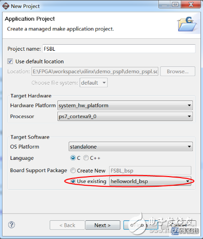
The project name is FSBL from here. Note that the board support package below selects the one you already have. Do not create new ones. Then Next, the following figure appears: 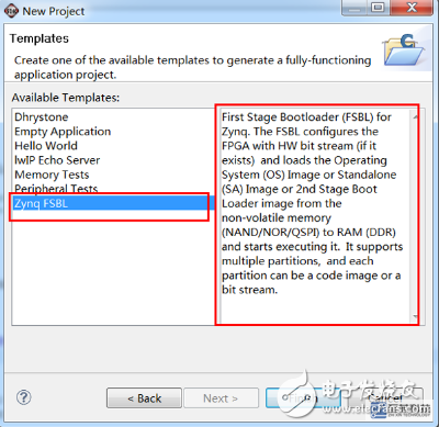
Pay attention to choose the bottom "Zynq FSBL", the right side will have its role explained. After clicking Finish, the FSBL file is generated and it is automatically compiled by default.
Generate image file
In the menu bar, select "Xilinx Tools - Create Zynq Boot Image", the following dialog box appears: 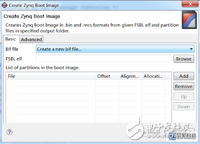
Here, we first click on "Browse", select the FSBL file we have just created, the suffix is ​​elf, in the Debug directory in the FSBL directory you created, here is FSBL.elf. Then click "Add" below to add the .bit file for configuring the FPGA, here system.bit. The same method then adds our application file, here helloworld.elf. And then determine the following "Output folder" directory (if you do not see this option, the above dialog box will be enlarged, it came out), when the directory is selected, try to select the directory without the Chinese path, select here is C Disk output directory (if you are wrong, then change to another disk directory, C disk may not have permission). After all the configuration is completed, as shown below, click on "Create Image". Under normal circumstances, you can generate the required files. Here we must pay special attention to the order of the three files, must not be wrong - first is the FSBL file, followed by the. Bit file, and finally the application file.
We open the output directory we just specified. There are three files: bootimage.bif, helloworld.bin, and helloworld.mcs. The second file helloworld.bin is the file needed to start from the SD card. Place the file on the SD card and set the development board to boot from the SD card. The third file, helloworld.mcs, is a file that is launched from Flash. It needs to be burned to Flash, and then select the development board to boot from Flash.
Burning method is as follows: In the SDK, select "Xilinx Tools - Program Flash", the following figure appears: 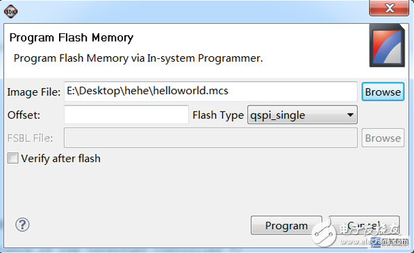
Click Browse, select the mcs file, and then click on the Program.
About how to set the board to start in what way, participate in the following table: 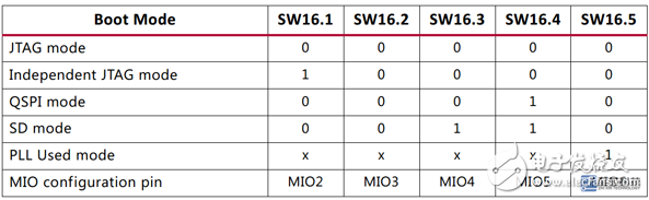
battery management through RS485 communication or CAN communication, and inverter power supply/ UPS power supply and other equipment are perfectly compatible and can be widely used in various 48V energy storage power systems
S/N
Item
Content
1
product type
Modular 48V large-capacity energy storage power system
2
Module model
48V200Ah
3
Weight
430kg
4
System capacity
200Ah*Parallel number(200~2000Ah)
5
Module dimension
19-inch standard cabinet width, thickness 5U, depth 480
6
Maximum continuous charge and discharge current
0.75C
7
Installation method
Pedal models, seat bucket models, etc.
8
IP rating
Module IP20, system power box can be customized IP65
9
Service life
10 years or 3000 cycles
10
Operating temperature range
Temperature: -20~60℃ Humidity: ≤85%RH
11
product description
The product is positioned as an energy storage power supply system, in accordance with the ultra-long storage/cycle life, modular design, can be connected in parallel according to the required system capacity, and can realize battery intelligent monitoring and
14
certificate
MSDS,ISO9001,CB,UN38.3