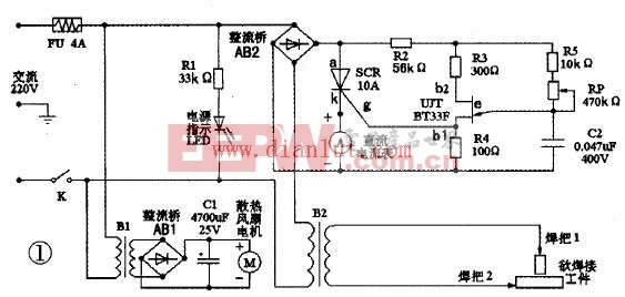
The AC spot welder is a machine that can hold workpieces together. The AC spot welder consists of a step-down transformer, a current regulator and a heat sink system, as well as accessories such as welding leads and handles. It is not necessary to use the welding electrode when welding. It is only necessary to use the two workpieces to be welded as the two electrodes of the circuit, and use the high temperature generated at the contact resistance to melt the metal instantaneously, thereby firmly welding the workpiece together. In the process of amateur electronics production and maintenance, it is inevitable to encounter welding battery pole pieces or thin steel plates, and to ensure the smooth completion of this task is inseparable from the welding machine. Electric welding machines can be generally divided into DC welding machines and AC welding machines. AC welding machines are composed of step-down transformers, current regulators and heat dissipation systems, as well as welding wires and handles. It is not necessary to use the welding electrode when welding. It is only necessary to use the two workpieces to be welded as the two electrodes of the circuit, and use the high temperature generated at the contact resistance to melt the metal instantaneously, thereby firmly welding the workpiece together. Circuit working principle As shown, B2 is a step-down transformer. The AB2 rectifier bridge, the unidirectional thyristor SCR, the single junction transistor UJT, the resistors R2, R3, R4, R5, the capacitor C2 and the potentiometer RP constitute a welding current stepless regulator. The DC ammeter A is used to indirectly indicate the magnitude of the welding operating current. Just form a power indication circuit with the LED. The small transformer B1, the rectifier bridge AB1, the capacitor C1, and the fan M constitute a heat dissipation system. It can be seen from the figure that the device circuit is very simple. It uses the negative-impedance characteristics of a single-junction transistor to form a relaxation oscillator as a trigger circuit for a unidirectional thyristor. Since the power supply of the single-junction transistor relaxation oscillator is taken from the full-wave pulsating DC voltage output from the bridge rectifier circuit. When the thyristor is not turned on, the capacitor C2 of the relaxation oscillator is charged by R2, R5 and RP, and the voltage VC2 across the capacitor rises exponentially. When going to the peak-point voltage VP of a single junction transistor. The single junction transistor UJT is suddenly turned on, and the base region resistance RB1 is drastically reduced. Capacitor C2 is rapidly discharged to the resistor R4 through the PN junction, causing a positive transition of the voltage Vg across R4. A steep rising edge of the pulse is formed, and as the capacitor C2 discharges, VC2 decreases exponentially, and when it is lower than the valley voltage V, the single junction transistor is turned off. The output of the R4 is a cusp trigger pulse. The thyristor SCR is turned on. An alternating current flows through the primary winding of B2, and the voltage drop across the thyristor becomes small, forcing the relaxation oscillator to stop working. When the AC voltage crosses zero, the thyristor is forced to turn off. The relaxation oscillator is energized again, and the capacitor C2 starts to charge again, so that the above process is repeated over and over again. Adjusting the potentiometer RP can change the charging time of the capacitor C2, so that the voltage applied across the B2 primary winding changes. Finally, the purpose of regulating the secondary output current is adjusted. Device selection and testing The step-down transformer B2 selects the filament transformer of the end-of-life high-power amplifier tube FU-720F of the waste color TV transmitter. The primary AC voltage is 220V. The secondary AC voltage is 4 V. Stable output current up to 80A. The single-junction transistor is BT33F, and the unidirectional thyristor is CR10AM. Before the actual production, it is necessary to check the quality of the pin electrode. For single junction transistors. First, determine the emitter e, put the pointer multimeter resistance file in the RX 1k file, and use the two meter pens to measure the positive and negative resistances of any two electrodes are equal (about 2 ~ 1OkΩ), the two electrodes are B1 and b2, the remaining one electrode is the emitter e, then the first base b1 and the second base b2 are distinguished, the black meter is connected to the E pole, and the other two electrodes are sequentially contacted by the red test pen, respectively, and the positive direction is measured. resistance. Due to the construction of the tube, the second base b2 is close to the PN junction, so the forward resistance between the emitters e and b2 should be slightly smaller than the forward resistance between e and b1, ranging from a few to a few ten kΩ. Therefore, when the measured resistance is small, the electrode connected to the red test pen is b2. When the resistance is large, the red test pen is connected to b1. But even b1 and b2 are upside down. Under normal conditions, the tube will not be damaged. It only affects the amplitude of the output pulse; if the amplitude of the output pulse is found to be small. Simply swap the two bases together. The unidirectional thyristor looks like a high-power triode. When the anode (a), cathode (k) and gate (g) three-electrode pins are discriminated. To use the pointer type multimeter R × 10 file. The DC ammeter A can be replaced by an easy-to-buy milliampere meter followed by a long wire. The wire is equivalent to a small resistance shunt resistor. The specific length should be determined according to the actual use of the display situation. After the circuit is assembled, it should be placed in a suitable metal casing. In addition to ensuring good ventilation, the entire circuit should be well insulated from the casing, and the casing must be reliably grounded. Precautions for use Connect the three-pin plug to 220V mains and close the power switch K. The power indicator LED lights up. At the same time, the cooling fan starts to work, and the potentiometer RP knob is turned to adjust the proper welding current to perform the welding operation. Operate the welder to understand and master the knowledge of safe electricity use. Part of the line with mains is insulated reliably. The welding wire is connected to the welding machine and the welding tongs, and the bolts and nuts are applied, and the gasket is tightened. The inside of the welding machine must also be inspected regularly, and the connection is found to be loose or desoldered, and should be tightened and welded in time. Lithium-ion Battery For Mechanical Equipment Lithium Ion Battery,Lithium Car Battery,Lithium Ion Battery Price,Lithium Battery Price Shenzhen Zhifu New Energy Co., Ltd. , https://www.sunbeambattery.com