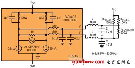
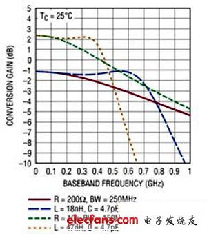
introduction Zero-IF receivers are not new; they have been used by people for a long time, and cellular phones are an important application area. However, its use in high-performance receivers such as wireless base stations has few successful cases. This is mainly because their dynamic range is limited and they are not well understood. A new wide-bandwidth zero-IF I / Q demodulator helps alleviate the lack of dynamic range and bandwidth of the main receiver and DPD (Digital Predistortion) receiver, and enables 4G base stations to cost-effectively Meet the growing bandwidth requirements of mobile access. The topic discussed in this article is: How to suppress the IM2 nonlinearity and DC offset that reduce the dynamic range of the zero-IF receiver as much as possible to achieve performance optimization, thereby providing a viable alternative for difficult designs. Promote the continuous expansion of bandwidth Until recently, most base stations only needed to handle a 20MHz wide channel bandwidth (often assigned to different wireless carriers). Associated with this 20MHz channel is a matching 100MHz bandwidth DPD receiver for measuring up to 5th order intermodulation distortion spurious signals to provide effective distortion cancellation. These requirements can usually be effectively met with high IF (heterodyne) receivers. However, as the industry is increasingly eager to hope that the base station supports the operation of the entire 60MHz frequency band, the difficulty of such design is now greatly increased. For the entire wireless manufacturing, installation and deployment business model, the completion of this great project is of great significance in terms of cost savings. In order to adapt to three times the bandwidth, the bandwidth of the DPD receiver must also be increased from 100MHz to 300MHz. In the 75MHz band, the DPD bandwidth has increased to an astonishing 375MHz. Designing a receiver that can support this bandwidth is not a trivial task. Noise will increase as the bandwidth expands, gain flatness becomes more difficult to achieve, and the required sampling rate of the A / D converter will increase significantly. In addition, the cost of such a high-bandwidth component is much higher. The high bandwidth of traditional high-IF receivers is no longer sufficient to support 300MHz or higher frequency DPD signals with a typical gain flatness of ± 0.5dB. The baseband bandwidth of 300MHz will require the selection of a minimum IF frequency of 150MHz. It is not an easy task to find an A / D converter with a sampling rate that can exceed 600Msps and at a reasonable price (even with a 12-bit resolution). Users may be forced to take a compromise and use a 10-bit converter. New I / Q demodulator relaxes bandwidth constraints Linear Technology ’s LTC5585 I / Q demodulator is designed to support direct conversion, thus allowing the receiver to demodulate the above 300MHz wide RF signal directly to baseband (see side note: How Zero Intermediate Frequency Receivers Work). The I and Q outputs are demodulated into a 150MHz bandwidth signal, which is only half the bandwidth of the high IF receiver. In order to obtain a passband gain flatness of ± 0.5dB, the device's -3dB corner frequency must be extended far above 500MHz. The LTC5585 supports this wide bandwidth with a tunable baseband output stage. The differential I and Q output ports have a 100Ω pull-up resistor to VCC in parallel with a filter capacitor of about 6pF (see Figure 1). This simple RC network allows the formation of an off-chip low-pass or band-pass filter network (to eliminate high-level out-of-band blockers) and equalizes the gain roll-off of the baseband amplifier link after the demodulator. In addition to the external 100Ω pull-up resistor, a 100Ω differential output load resistor is used, and the -3dB bandwidth can reach 840MHz. Figure 1: Equivalent circuit of baseband output for bandwidth expansion (using L = 18nH and C = 4.7pF) Baseband bandwidth expansion A single LC filter section can be used to expand the bandwidth of the baseband output. Figure 1 shows the chip baseband equivalent circuit with the baseband bandwidth extension function. With a 200Ω load, an 18nH series inductance and a 4.7pF parallel capacitor can extend the -0.5dB bandwidth from 250MHz to 630MHz. Figure 2 shows the types of output responses that may be generated under different load conditions. One of the responses was obtained using 200Ω and 10kΩ differential load resistance. For a 10kΩ load, a 47nH series inductance and a 4.7pF parallel capacitor can extend the -0.5dB bandwidth from 150MHz to 360MHz. Figure 2: Conversion gain versus baseband frequency (using differential load resistance and LC bandwidth extension) Poe Adapter,Ubiquiti Poe Adapter,Carrier Poe Adapter,Poe Power Adapter Guang Er Zhong(Zhaoqing)Electronics Co., Ltd , http://www.gezadapter.com