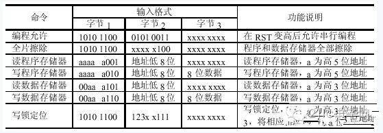
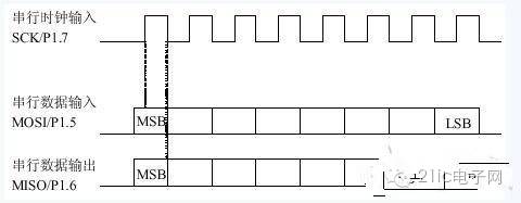
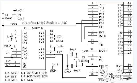
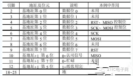
The old-fashioned topic has come again. I feel that I have seen a lot of different kinds of MCU development experience, but those are not necessarily suitable for you. "Reading books a hundred times is right and self-seeing", and we are endless on the road to pursuit of learning. . The initial exploration of microcontroller development has taken the longest time to do AT89C5X (51, 52, 55, etc.), and I may know more. I mainly talk about the experience and lessons in practical applications. For the book, please refer to a book dedicated to AT89 series published by Beihang University. It is not bad. I suggest you buy it. AT89C51 I think it is a very standard 51 single-chip microcomputer, 4 P ports, 1 serial port, RAM only standard 128Byte, Flash only 4K, the function is quite complete, I use it as the basis, so I encountered it during the development process Question it. The problem of reset source, the most commonly used reset method is resistance and capacitance. AT89C51 is a high-level reset. This method is unstable and can be used during product debugging. Because we generally use an emulator when debugging, and many emulations The device will output the reset signal by itself, and shield the reset signal generated by the target board, so there is no problem with the reset signal during debugging. Our company uses Changsha Juyang's emulator, which uses more advanced technology, which is not bad. , There is no problem with the simulation of AT89 series chips, and it is very stable. Here is a very important question to talk about. Sometimes you will encounter such a problem: your own program runs without any problems during simulation, but it doesn't work after burning. There are two reasons for combining my experience. First, the timing may have changed. Everyone knows this. I won't say much. Another reason is the reset signal. Details are as follows: (1) There is a problem with the reset circuit, and the reset signal cannot be generated normally. Because the emulator may provide you with a reset signal during debugging, but it will disappear after leaving the emulator; (2) The problem of watchdog. Some 51 chips have a watchdog reset function, such as At89c55WD. When the watchdog is turned on in the program, sometimes the initialization content of the program is too much, and a reset signal is often generated, especially when the C language programming function is used. At that time, although you obviously closed the watchdog somewhere at the beginning of the program, the program will still be reset. This is because the execution efficiency of C language is lower than that of assembly. It looks like a few lines of code and sometimes takes a long time. Be sure to pay attention to this problem when using the door opener. And this problem is easy to be ignored when using the emulator, because even if the watchdog in your program is reset, the emulator (Juyang emulator can enable/disable this function) often shields the reset signal, so the program is still It will run normally. When you burn the program and run it again, you find that the program you have just debugged cannot run normally. That's because your program has been resetting continuously. Note that you may not see the reset when you observe the RST pin with an oscilloscope. Signal, because the watchdog reset does not affect the level of the RST pin. Another situation is that there is no watchdog inside the chip, but there is a CPU monitoring chip in the circuit. It can often provide a reset signal, and it is a reset signal for many reasons. If you find the above situation, you can use an oscilloscope Check the RST pin to see if there is a level change. Therefore, it is recommended that you use the CPU monitoring chip as much as possible when developing 51 products. X5045 is very easy to use, because it also has Eprom function. This is used in many occasions, and you can also use a dedicated reset chip such as MAX708. Stable and convenient. Summary of notes The following is a summary of a few notes that I have made based on my actual situation: 1. Calculation and selection of the resistance (exclusion) in series with the light-emitting diode. Generally, the normal light-emitting current of the light-emitting diode is 3~10mA, which is generated on the light-emitting diode. The voltage drop is 1.7V (rail tube) R=(5-1.7)/3~10 (k) 2. The TTL level of the single-chip microcomputer is high level: +5V; low level: 0V. RS232 serial port high level: -12V; low level: +12V. The MAX232 level conversion chip can be used to convert the level between. 3. The register of the I\O port of the single-chip microcomputer is high level, and the other registers are low level. 4. The switching function of the triode: In the indirect forward voltage of B and E, E and C are conducting. 5. Buzzer: 1) The active buzzer can sound continuously when connected to the rated voltage directly. 2) Passive buzzer, like electromagnetic speaker, needs to be connected to the audio output circuit to make a sound. 3) The active buzzer has an oscillation source, but the passive buzzer does not. 4) The ideal signal of an active buzzer is direct current. 5) The ideal signal of the passive buzzer is a square wave signal. Square wave sound function: void beep(){ fmq=0;delay 500us();fmq=1;delay 500us();} 6. Calculate the instruction cycle of the microcontroller: instruction cycle (us) = 12 / crystal oscillator frequency (Mhz) selection A 12M crystal oscillator, a chip with a command cycle of 1us7 and 89C51 supports up to 24M crystal oscillators. It’s just the author’s crude insights from the previous generations. The author and everyone will feel that it is not very enjoyable. The stone of the mountain can be used to attack jade. We still need to learn from more predecessors. After sorting out the experience of the predecessors, the author has seen a lot of development experiences that are worth sharing with a large family! At present, there are many articles about the application of single-chip microcomputer, but there are few articles about the production of single-chip development tools. Because the single-chip microcomputer is a very practical course, if the traditional development mode is adopted, it is necessary to purchase expensive emulators, programmers and other development tools for experiments. In fact, due to the increasingly perfect chip functions, we can use the chip's in-system programming (ISP) function to create practical and low-cost development tools. The following is to help DIY enthusiasts develop and produce suitable development tools. 1. The current common development mode At present, there are basically two development modes to choose from: using an emulator and using a programmer. ①Use an emulator. Advantages: Convenient, breakpoints can be set, and the contents of memory and registers can be observed. Disadvantages: expensive, different types of single-chip microcomputers need to buy different emulators; after all, the emulator is not a single-chip microcomputer, and sometimes the code can pass on the emulator, but it cannot work normally in the single-chip microcomputer, which increases the difficulty of debugging. ② Use the programmer. Advantages: The price is relatively cheap, usually one programmer can program multiple devices. Disadvantages: The operation is quite inconvenient. You must transfer the chip between the target board and the programmer every time, and you have to switch between the compiler operation interface and the programmer operation interface. Most of the time, simple repetitive work is done. 2. Introduction of new development model and chip selection The development tools introduced in this article use a new development model (similar to the programmer development model). Since the in-system programming function of the chip is utilized, there is no need to move the chip. In the software design, it is designed that once the code file is reprogrammed, it is automatically downloaded to the chip and automatically reset to run, which is a real "what you compile is what you get." Many microcontrollers currently support in-system programming. There are many 8051 series single-chip microcomputers that support in-system programming, but most of them support the programming of the single-chip microcomputer through the serial port of the PC. There are four inconveniences in this way: one is the inconvenience of serial communication between the project itself and the PC; the other is to add a MAX232 level conversion chip; the third is that some chips need to enter the download mode according to specific steps and the programming process Manual intervention is required; fourth, some chips need the support of firmware (customized program). If the firmware is accidentally damaged, the in-system programming function of the chip will also be lost. After comparison, AT89S8252 produced by Atmel is an ideal chip suitable for making development tools. This chip has the following features: ◆It is compatible with 8051; ◆It contains 8KB of program memory that can be erased and written for 1000 times, 2KB of data memory that can be erased and written for more than 100,000 times, and 256 bytes of 8-bit wide internal RAM; ◆ It can pass SPI interface In system serial programming, compatible with 8051 ◆ There is an automatic erasing cycle during serial programming, and can be downloaded in sections when debugging large programs, saving time; ◆ Low voltage download, no 12V programming voltage. 3. AT89S8252 serial programming (1) AT89S8252 serial programming mode When the RST pin of the chip is set to high level, all programs and data memory can be programmed through the SPI bus interface [SCK, MOSI (input), MISO (output)]. After RST goes high, a programming permission command must be sent first before programming or erasing operations. In serial programming mode, the chip will automatically insert an erase cycle before byte programming. Therefore, unless the code protection bits of the chip are programmed, there is no need to execute a full chip erase command before programming. The SCK clock frequency of the SPI interface must be lower than 1/40 of the crystal oscillator frequency. (2) AT89S8252 serial programming steps ①Connect a 3~24MHz crystal oscillator between XTAL1 and XTAL2; add power supply voltage before VCC and GND, set RST high, and wait for 10ms. ② Send the serial programming permission command. ③ Send commands and data such as write/read/erase. The high bit of the serial data is in the front and the low bit is in the back. The data is locked on the rising edge of the clock. ④ If the previous step is to write a command, wait at least 2.5ms. ⑤ Repeat steps ③ and ④ if necessary. ⑥ Set RST low and the chip starts to run. (3) AT89S8252 serial programming commands, AT89S8252 serial programming commands are listed in Table 1. (4) AT89S8252 serial programming timing diagram, AT89S8252 serial programming timing diagram shown in Figure 1. 5. Parallel port control with VB programming The base address of the print port is generally 0x278, 0x378 or 0x3BC, which can be found from the control panel. For the convenience of readers, Table 2 lists the descriptions of commonly used printer port pins and register bits. Table 2 In the Windows environment, the easiest and easy to learn language is probably VB, so our development tools also use VB as the programming language. However, due to the protection of Windows, VB cannot directly read and write the print port, so we need another program module to realize the direct read and write of the print port. Many such modules can be found on the Internet, and quite a few modules can be used for free. After trial, I recommend Winio v2.0. This module supports Win9X/NT/2000/XP (http:// Yariv Kaplan), and comes with detailed help, example programs and source code. When using, copy the four files Winio.sys, Winio.dll, Winio.vxd and Winio.bas to the working directory, and add the Winio.bas module directly in VB. There are four functions used in this example, which are explained as follows. ①IniTIalize(): Allow port control function. Call it once before using the port input and output function, and return "1" if it succeeds, and return "0" if it fails. ② Shutdown (): Shut down the port control function. It is executed once when exiting the program, and returns "1" if it succeeds, and returns "0" if it fails. ③ GetPortVal (ByVal PortAddr As Integer, ByRef Portval As Long, ByVal bSize As Byte) As Boolean: Read the port function, PortAddr is the port address, Portval is the port value, and bSize is the number of bytes to be read. It returns "1" when the reading is successful, and "0" when it fails. ④ SetPortVal (ByVal PortAddr As Integer, ByVal Portval As Long, ByVal bSize As Byte) As Boolean: write port function. PortAddr is the port address, Portval is the value to be written, and bSize is the number of bytes to be written. If writing is successful, it returns "1", and if it fails, it returns "0". The declaration of the four functions in the Winio.bas module is as follows: Declare FuncTIon IniTIalizeWinIo Lib "WinIo.dll" () As Boolean Declare FuncTIon ShutdownWinIo Lib "WinIo.dll" () As Boolean Declare Function GetPortVal Lib “WinIo.dll†(ByVal PortAddr As Integer, ByRef Portval As Long, ByVal bSize As Byte) As Boolean Declare Function SetPortVal Lib “WinIo.dll†(ByVal PortAddr As Integer, ByVal Portval As Long, ByVal bSize As Byte) As Boolean 6 Intel HEX format file Because the files used to write chips produced by general compiling software are all files in Intel HEX format. Intel HEX files are text files and can be viewed with Notepad. One line of an Intel HEX file is called a record, and each record is composed of hexadecimal characters, and two characters represent the value of a byte. Intel HEX files usually consist of several records, and each record has the following form: : LLAAAATTDD.. .DDCC ":"-the starting mark of the record; LL-record length, indicating the number of data bytes in the record; AAAA——The first address of data loading (16 bits); TT——Record type, 00 means data record, 01 means end of file; (Note: some compiling software will produce record type greater than 01, this application can ignore the record type greater than 01.) DD——Data value (byte); CC-checksum. (Adding itself to all bytes in the record except the start flag should be 0, if it is not 0, there is an error.) For detailed instructions on VB programming, please refer to the supplementary version of this journal (http://). (Because the flow of each subroutine is relatively simple, the source code is given directly without drawing a flowchart. The program adopts a bottom-to-top design method.) Conclusion Although the above program can realize various basic functions, it is not perfect, and various abnormal situations are not considered. Readers can improve it according to the actual situation. Because the price of AT89S8252 is still relatively expensive, it is difficult to buy on the market now, but AT89S51/52, which is introduced by Atmel, which replaces AT89C51/52, also has in-system programming functions and is cheap. The implementation method of its in-system programming is similar to AT89S8252, and the device can be supported by slightly modifying part of the program in this example. The "MCS51/AVR/PIC three-in-one downloader" made by the author adds support for AT89S51/52. Because the execution efficiency of C language is lower than that of assembly, it looks like a few lines of code, and sometimes it takes a long time, so you must pay attention to this problem when using the open dog. And this problem is easy to be ignored when using the emulator, because even if the watchdog in your program is reset, the emulator (Juyang emulator can enable/disable this function) often shields the reset signal, so the program is still It will run normally. When you burn the program and run it again, you find that the program you have just debugged cannot run normally. That is because your program has been resetting continuously. Note that you may not see the reset when you observe the RST pin with an oscilloscope. Signal, because the watchdog reset does not affect the level of the RST pin. Another situation is that there is no watchdog inside the chip, but there is a CPU monitoring chip in the circuit. It can often provide a reset signal, and it is a reset signal for many reasons. If you find the above situation, you can use an oscilloscope Check the RST pin to see if there is a level change. Therefore, it is recommended that you use the CPU monitoring chip as much as possible when developing 51 products. X5045 is very easy to use, because it also has Eprom function. This is used in many occasions, and you can also use a dedicated reset chip such as MAX708. Stable and convenient. Shenzhen ChengRong Technology Co.,Ltd. , https://www.laptopstandsupplier.com