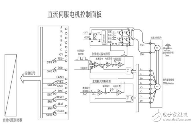
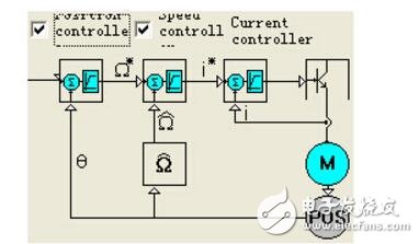
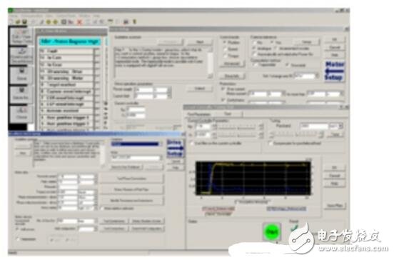
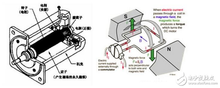
The servo control system is an operating system that can automatically control the mechanical movement of the test device according to predetermined requirements. In many cases, the servo system refers to a feedback control system in which the controlled amount (output of the system) is mechanical displacement or displacement velocity and acceleration, and its function is to make the mechanical displacement (or rotation angle) of the output accurately track the displacement of the input ( Or corner). There is no principle difference between the structural composition of the servo system and other forms of feedback control systems. DC servo is similar to AC servo, and can be controlled by controller open loop control, controller semi-closed loop control and full closed loop control system. The structure of the DC servo system control panel is as follows: the right side of the panel is the interface with the DC servo motor interface board, including the motor drive interface and the encoder interface; the left side is the interface with the motion controller panel, including the position control mode interface and the speed control mode. interface. The M+, M-signal is the power line for the DC brushless servo motor and is used to drive the motion of the motor. The A+, A-, B+, B-, C+, C-, 5+, 0V signals are encoder signals that are used to feed back the actual position of the motor shaft. A, /A, B, /B, C, /C, +5V, PUL+, DIR+, OGND, OVCC, GND, DAC, RESET, ALM, ENABLE are control signals connected to the controller. Its meaning is: A, /A, B, /B, C, /C are the encoder signals that the driver feeds back to the motion controller. +5V is the power supply. PUL+, PUL- is a pulse signal for motor control in position mode. DIR+, DIR- is the direction signal for motor control in position mode. OGND, OVCC, and GND are analog ground, analog power and digital ground. The DAC is the analog control signal that the driver accepts, typically ranging from -10V to 10V. RESET, ALM, and ENABLE are control signals that indicate the reset, alarm, and enable functions of the drive. DC servo drives typically have a speed control mode and a position control mode. When using the position mode, the input control signal is pulse and direction (either positive and negative pulse). When using the speed mode, the input control signal is analog. The driver converts the input signal into a speed control signal, which is converted into a current control signal by a speed controller. The current signal is applied to the output module of the power expansion module through a PWM loop and finally applied to the motor. DC servo drives use IDM only servo drives. IDM240/640 is an embedded intelligent, high-precision, all-digital servo driver that can drive square wave or sine wave brushless servo motor (PMSM), DC servo motor, and can form up to 256 via CAN or RS-485 interface. The axis's distributed intelligent network motion system, embedded in Advanced Programmable Motion Language (TML), offers a variety of advanced motion control and plc-specific functions. The main features are as follows: Distributed intelligence, single-axis master operation or slave axis mode Control mode: position, speed, torque, voltage, external variable Sport mode: Pulse + Direction, Electronic Gear, Profiling, Contouring Programmable protection: position error, overcurrent, overvoltage or undervoltage, I2t, DSP Control Technology: Based on MoTIonChipTM Technology RS232/485 serial interface, baud rate up to 115KB CAN2.0 local bus, compatible with CANopen, baud rate up to 1MHz Output current: continuous current 5A/8A, peak current 16A, Power supply voltage: 12-48VDC (IDM240), 12-48VDC (logic power supply) / 80V (motor) (IDM640) Compact design: 136 x 84.5 x 26 mm The control software uses Easy MoTIon Studio, and the control software features are as follows: Advanced graphical evaluation and analysis programming tool EasyMoTIon Studio platform to quickly set the motor, drive parameters and programming motion program, TML_LIB function library is a function library of intelligent servo drive to perform motion control applications on PC, in C / C + +, Basic, Delphi, After the LabVIEW development application calls the .DLL file in the library, it can directly communicate with the driver, set parameters, query status, transfer commands, define motion events, and test the status of input and output ports. Starter Kit for IDM640: Contains the complete components of the drive, including an IDM640 drive, a motor, an I/O board, EasyMoTIon Studio software, and application help and complete documentation. It is the ideal experimental platform for testing your motion control program. Both are included in a ready-to-run, plug-and-play component as described above. The DC servo motor consists of the following components: Stator: Magnetic field - permanent magnet Rotor: armature winding Reversing: commutator and carbon brush The DC power supply applied to the DC motor, by means of the action of the commutator and the brush, causes the current flowing through the armature coil of the DC motor to be alternating, so that the direction of the electromagnetic torque generated by the armature is constant. Make sure that the DC motor rotates continuously in the determined direction. DC servo advantages: • Precise speed control • Torque speed characteristics are very hard • Simple principle and easy to use • price advantage Disadvantages: • Brush commutation • Speed ​​limit • Additional resistance • Produces wear particles (for clean rooms) Large Area Of Mid-rise Building Sky Curtain Large Area Of Mid-Rise Building Sky Curtain,Media Facade Led Display,Led Waterproof Stage Screen,Custom Screen Size Led Panel Display Kindwin Technology (H.K.) Limited , https://www.ktlleds.com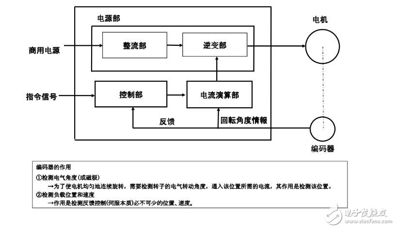
Introduction to servo control system The composition and control principle of DC servo system