Simple open circuit protection for boost converters in LED driver applications
One way to drive high-brightness LEDs is to modify the standard boost converter topology to drive a constant current through the load. However, there is a serious problem with this implementation method, because an open fault in the LED string will remove the load current path. Due to the high output voltage from the converter, which operates at no feedback at this time, this may cause potential damage to the circuit. This article introduces you to a simple and robust open-circuit fault protection method that uses a Zener diode and a resistor and has a negligible effect on the overall efficiency. By configuring a high-voltage boost converter as a constant-current driver for driving three high-brightness white LEDs and generating a simulated fault state at the output, we can verify the functionality of this topology. The circuit controls the output voltage to a certain safe level and reduces the output current in the protected state.
Typical high-brightness LED boost converter
We often modify the converter to drive high-brightness LEDs in single-cell Li-Ion, alkaline, and other applications. In these applications, the voltage of the LED string exceeds the battery or power rail voltage. In the standard boost configuration structure, a voltage divider is used to generate the feedback voltage VFB of the circuit, thereby monitoring the output voltage VOUT. The converter regulates the output voltage so that VFB is always equal to the on-chip reference voltage VREF. This topology is adaptive and can replace the upper resistor in the feedback voltage divider with a load to maintain a constant current instead of a constant voltage, as shown in the LED string in Figure 1. The load current depends on the on-chip reference voltage of the boost converter, and its calculation method is as follows:
A serious problem with this simple implementation method is that an open fault in the LED string will remove the path of the load current. When no current flows through the feedback resistor RSET, VFB is pulled down to ground. In response, the boost converter will increase its duty cycle to its maximum value as much as possible in order to maintain the correct voltage on the feedback (FB) pin. Using the idealized boost converter transfer function shows that a high output voltage (VOUT) can be generated when the converter is close to its maximum duty cycle. Consider a 90% (commonly used value) typical maximum duty cycle and 5V input boost converter:
![]()
The high voltage at the output of the converter brings the possibility of multiple failures. This voltage may exceed the ratings of internal or external switching devices or passive components. In addition, if the circuit is operated without taking protective measures, it will also bring potential danger to the user and may damage the load when connected.
Figure 1 High-voltage boost converter structure of LED driver without open circuit protection
protect the circuit
When an open circuit occurs, the load current must have a backup path. Although connecting a resistor in series with the LED can provide a path, it is not ideal because it causes a huge loss of efficiency. The alternative configuration (Figure 2) consists of a Zener diode and a resistor to provide adequate system protection with minimal loss of efficiency.
Figure 2 LED driver circuit with open protection
When the load current path is removed, the output voltage rises until the Zener diode ZD1 turns on, and current flows through RPRO and RSET to ground. The output current is determined by the series combination of RPRO and RSET because VFB is driven to equal the internal bandgap reference voltage VREF. Therefore, the output protection current defaults to:
![]()
We choose a voltage for the Zener diode so that no current flows through it during normal circuit operation. To ensure that the diode is completely turned off during normal operation, the selected voltage should be at least 2V higher than the maximum load voltage, but less than the specified maximum output voltage of the boost converter. In this way, circuit designers are not often forced to increase the rated voltage of the output capacitors C2 and C3 and the clamping diode SD1. The output voltage is controlled as the sum of the Zener diode voltage and the reference voltage:
![]()
The RPRO value is selected by balancing the LED current sensing error and power consumption during circuit protection. In fact, the value of RPRO should be as large as possible to minimize the power consumption of the Zener diode:
![]()
The error entering the circuit is caused by the leakage current IZL of the Zener diode and the bias current IFB of the internal error amplifier of the boost converter. Equation 6 is a modified transfer function that includes these errors:

Since these two currents are generally less than 1 µA, the error caused is very small and can be ignored in most implementations.
Demonstration argument
As an application example, TI TPS61170 boost converter IC is configured as a constant current LED driver. In applications such as backlighting or flashlights, it is an ideal boost converter for driving high-brightness LED strings. The 3V-18V input range allows a wide range of power supplies, such as 2S to 4S lithium-ion or 3S to 12S alkaline battery packs, USB or 12V power rails.
Figure 3 Protection circuit activates oscilloscope screenshot
The boost converter is configured to drive 3 high-brightness white LEDs (260 mA). When the typical reference voltage is 1.229 V, the simplified load current is used in Equation 7 to calculate RSET:

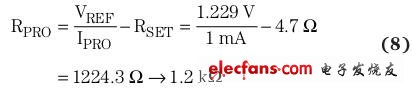
We choose the 1mA value as the protection current (IPRO) to calculate the RPRO value:
We chose a 15V zener diode for ZD1 to represent the minimum leakage current at an estimated load voltage of about 10V, while also controlling the output to a value well below the maximum allowable output voltage (40V) of the boost converter. The output voltage is controlled at the Zener diode voltage (VZD1), which is the sum of the converter reference voltage:
![]()
Using the selected load current and protection resistor, calculate the deviation from the expected load current (see Equation 10 below). The data sheet value is 200 nA for the feedback bias current (IFB), and the 1 µA value is used for the estimated Zener diode leakage current, VOUT is about 10V.
![]()
The target load current of the circuit is 260 mA. As we have seen, once the theoretical values ​​of the components are replaced by the effective values ​​in Equation 10, they will cause more errors than the protection circuit itself causes.
In order to test the operation of the protection circuit, we use a 38 Ω resistor decimal box instead of the LED string. The purpose is to simulate the voltage of the LED string under the design load current. By quickly changing the load resistance from 38 Ω to 1038 Ω, an open-circuit fault can be simulated. As shown in Figure 3, this change in output current (green line) indicates a sudden change in load impedance. To compensate, the TPS61170 output voltage (yellow line) rises to reach the designed load current again. However, this change will not remain the same until it reaches its maximum duty cycle, and the output voltage stabilizes at a clamping voltage of about 16V.
in conclusion
We have introduced a simple method for providing open circuit protection for a boost converter configured as a constant current LED driver. This circuit consists of a zener diode and an additional resistor, which limits the output voltage to a safe level, while reducing the output current when the load has an open circuit fault. In addition, this method brings some errors to the load current calculation process and slightly reduces the efficiency during normal circuit operation, but these effects can be ignored. Configure a boost converter as an LED driver and add a 15V Zener diode and a 1.2kΩ resistor for output protection. This demonstrates the functionality of this protection circuit. This demonstration demonstrates that the output performance of the circuit under simulated load fault conditions is in line with our expectations.
Cordless Barcode Scanner,Zebra Barcode Scanner Wireless,Zebra Cordless Scanner,Symbol Cordless Scanner
Guangzhou Winson Information Technology Co., Ltd. , https://www.barcodescanner-2d.com