The most important thing in the design and optimization design of stepping motor is the prediction of performance index. However, due to the special structure and operating conditions of stepping motor, people often make certain assumptions in the calculation process, such as ignoring the saturation of magnetic circuit or It is assumed that the magnetic pressure drop of the core portion is independent of the rotor position, etc., in order to be simplified, which naturally brings a certain error to the calculation result. In order to fully consider the influence of the saturation of the magnetic circuit of the motor on its performance, this paper takes the prototype BF36 magnetoresistive stepping motor as an example, adopts the finite element numerical solution method, and solves the whole motor by means of the mesh automatic splitting technology. Perform magnetic field analysis to obtain the magnetic common energy of the motor magnetic field, and then calculate the static torque of the motor. The difference between the stator and rotor tooth shapes of the reluctance stepping motor will affect the magnetic conductance of the motor magnetic circuit and the motor magnetic field, thus affecting the performance of the motor. 2 finite element numerical calculation of static torque characteristics The structure of BF36 three-phase reluctance stepping motor is shown in Figure 1. There are 6 magnetic poles on the stator, and there are 3 rectangular teeth on each pole. Zr= 20 evenly distributed rectangular teeth with a fixed rotor tooth moment of 18 degrees. The motor's U N = 24V, L N = 0.15A, can be energized in single phase or in two phases. Wire harness & Cable assembly:The terminal wire in the electronic machine can effectively solve the problem of control and wire diameter of equipment installation. In addition, the installation operation is more convenient and safe. It is mainly reflected in that the secondary wiring is not easy to start, and other secondary wires may be touched during connection; if the primary connection wire diameter is small, the wire diameter is too large. For the cabinet with high segmentation degree, the bending radius is a problem, and the stress problem will occur, The switch may be damaged; in addition, the wire nose required by the installation specification may be greatly larger than the installation point of the component itself, and these terminal machines can effectively solve the problem. Wire harness & Cable assembly ShenZhen Antenk Electronics Co,Ltd , https://www.antenkelec.com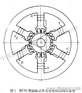 The static torque of the reluctance stepping motor is calculated by the numerical method of the limit and the element. The formula for calculating the electromagnetic torque can be directly utilized by the magnetic common energy of the motor magnetic field.
 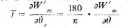 In the equation, θr is the angular displacement of the rotor, radθ is the angular displacement of the rotor. In order to calculate the static torque characteristic of the motor, that is, the moment angle characteristic, it is necessary to study the stator pole coil of the motor at different currents and when the rotor has different positions relative to the stator. The distribution of the magnetic field. Due to the range of pitch t,
  The position of the motor is symmetrical, so it is only necessary to study the half-pitch, that is, the magnetic field at various positions within 9 degrees. When the center line of the rotor tooth is aligned, θ=0. According to the structure of the motor, the mode of energization and the symmetry of the magnetic field, the space of the half motor can be selected as the solution area of ​​the motor magnetic field. Figure 2 shows the network of the solution area at this time. Splitting.
 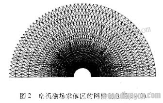 After a current is applied to the pole coil at a certain value of θ, the finite element calculation of the two-dimensional magnetic field can be used to obtain the vector magnetic position A value of the internal nodes of the solution region, the magnetic flux density of each unit, and the magnetic lines of force of the solution area. distributed. Figure 3 shows the distribution of magnetic lines of force when A and B are the same when θ = 1 degree, and then the post-processing calculation can be used to find the total flux linkage of the chain of the energized pole coil. Then, the value of the current is changed, and the new magnetic flux value of the magnetic field at the θ position and the åŒ chain of the magnetic pole coil is calculated. In this way, after repeated calculations, a set of different currents and the resulting magnetic pole coil flux linkage can be obtained, that is, the relationship between the current of the motor and the flux linkage of the coil at the rotor position θ is obtained ψ=f(I ).
 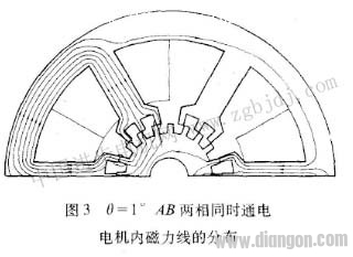 If the rotor rotates 1 degree in the clockwise direction from θ=0, repeat the above calculation until θ=9 degrees (this is easy to implement in the finite element numerical analysis by means of the mesh auto-split technique). ), which gives the relationship between the flux linkage and current of the motor in all 10 fixed rotor and rotor positions. Fig. 4 is a ψ=f(I) curve of the motor when θ = 0 and θ = 1 degree in the energized state of the A-phase winding. Therefore, the magnetic common energy Wm of each θ position at a certain current can be obtained by the Simpson integral method '3', for example, I=I N = 0.15A, and the magnetic collateral value at θ=0 is the curved shape oaco. The area, θ = 1 degree, the magnetic common energy is the area of ​​the curved obco. By repeating the above steps, the magnetic sensitivities of the 10 electric gauges corresponding to θ=0.1 degrees. 2 degrees...9 degrees at this current can be obtained, that is, there are 10 sets of corresponding values ​​in which Wm corresponds to 0. Then, the magnetic common energy Wm can be obtained by using the differential equation (4) of the cubic spline interpolation function. For the θ derivative, and according to the formula (I), the static torque characteristic curve T=f(θ) of the stepping motor can be obtained. Figures 5 and 6 show the static torque characteristics calculated when the motor is energized at the rated current for single-phase energization and at the same time. Fig. 7 and Fig. 8 respectively show the corresponding measured results. In comparison, the maximum static torque error is 5.41 percent for single-phase energization and 7.34 percent for two energizations at the same time.
 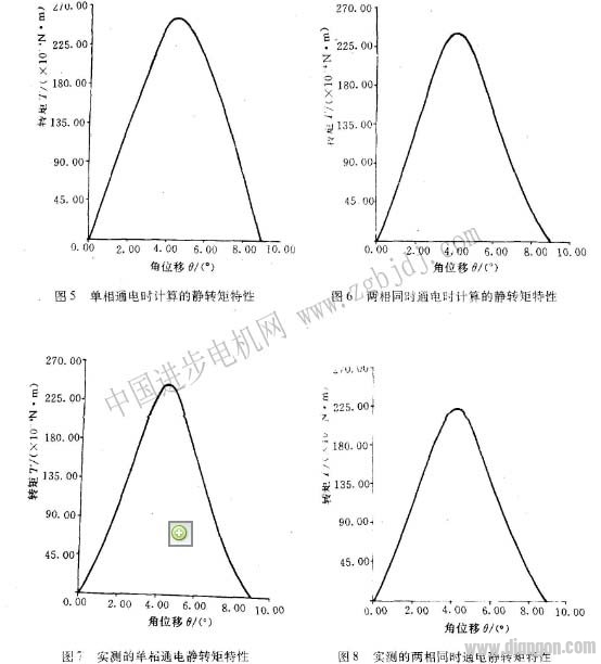 3 The influence of the tooth profile on the maximum static torque. Some basic researches on the different stator and rotor tooth shapes of the motor have been carried out to find out their influence on the performance of the motor. The conclusion is that the shape of the stator of the stator should be rectangular. As well. However, in the tooth size, for example, there is an optimum fit between the tooth height, the pitch and the tooth width. For this purpose, we use different ratios of tooth height to pitch (for the same groove width). Time) and the ratio of the tooth width to the pitch (at the same slot height), the calculation of the maximum static torque, Table 1 and Table 2 respectively list their calculation results (both are the same power-on condition), Which represents the actual size of the prototype. It can be seen from the table that the rhythm of the magnetoresistive stepping motor has a tooth height as close as possible to the pitch, and the tooth width is about 37.5 percent of the tooth pitch.
 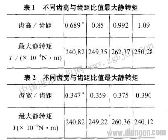 4 Conclusion a. In order to fully consider the saturation factor of the motor, this paper calculates the static torque characteristics of the reactive stepping motor with single-phase energization and two identical energizations, and the calculated values ​​are close to the measured values. This theoretical calculation method is correct. b. When the tooth height/tooth pitch ≈_l and the tooth width/tooth pitch ≈0.375, the reluctance stepping motor can obtain a large static torque, which can be referred to in the production of the factory.