Test and Analysis of Insulation Sleeve Failure before Putting High Voltage Isolation Switch into Operation
Before the high-voltage isolating switch was put into operation, a fault in the insulation bushing of the isolating switch was identified during routine testing. Based on the actual situation and past experience, the root cause of the fault was thoroughly investigated. Effective measures were taken to address the issue, with a focus on specific repair methods and preventive strategies to avoid future failures of the isolating switch.
Key words: Isolating switch; porcelain insulator failure; repair method
1. Accident Phenomenon
During the insulation test of the outdoor isolating switch GW1-12/2000A in a 10 kV system before commissioning, it was discovered that the insulation level of the C-phase blade was significantly lower than the required standards. This deviation from the specified insulation level posed a serious risk to the safe operation of the system, as it could lead to unexpected faults or even equipment damage.
2. Accident Analysis and Processing
The isolating switch is part of a larger electrical system, as shown in Figure 1. The front of the faulty isolating switch is connected to a current transformer, followed by a three-winding 10 kV step-down transformer. The isolating switch is connected to the transformer via a bronze busbar of 100×8 dimensions, while the secondary side cable of the transformer has not yet been connected.
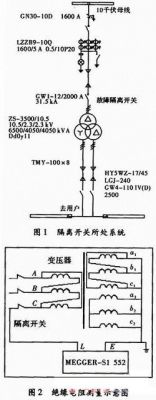
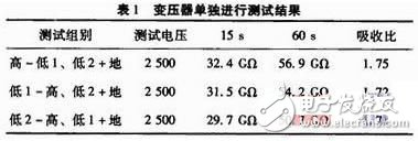
Both the isolating switch and the transformer were tested for insulation resistance using the MEGGER-S1-552 electronic megohmmeter. The test voltage was set at 2,500 V, following the standard procedure outlined in Figure 2.
The measured insulation resistance value was only 24.5 MΩ, which was far below the factory test data, where the insulation resistance was on the order of GΩ. This significant drop in insulation resistance raised concerns about the integrity of the isolating switch. After eliminating environmental factors such as temperature and humidity, the team decided to isolate the isolating switch and perform separate tests on the transformer to determine if any damage occurred during transportation or installation.
The individual tests on the transformer showed much higher insulation resistance values, with absorption ratios also within acceptable limits. These results were close to the factory test values, indicating that the transformer itself was in good condition. Therefore, the defect must have originated from the isolating switch.
Further tests were conducted on the isolating switch separately, with each phase tested individually. The test setup involved closing the blade, connecting the high-voltage end to the static contact of the blade, the low-voltage end to the base of the blade, and grounding the system. The test configuration is illustrated in Figure 3.
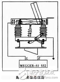
The insulation resistance measurement for the isolating switch remained low at 24.5 MΩ, confirming the presence of a fault. This result strongly indicated an issue with the insulation bushing of the isolating switch, likely due to internal contamination, cracks, or manufacturing defects.
To address this problem, the team performed detailed inspections of the insulation bushings and found that one of them had visible cracks and signs of moisture ingress. After replacing the faulty bushing and re-testing, the insulation resistance returned to acceptable levels, ensuring the safe operation of the isolating switch.
In conclusion, the fault in the isolating switch was traced back to the insulation bushing, and appropriate corrective actions were taken. To prevent similar issues in the future, the team recommended regular maintenance checks, improved sealing of components, and enhanced quality control during installation and transportation of critical equipment.
Shenzhen Essenvape Technology Co., Ltd. , https://www.essenvape.com