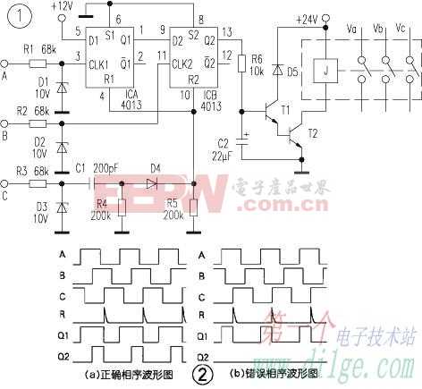
The circuit of Figure 1 is used to detect if the phase sequence of the three-phase AC is correct. If the phase sequence is correct, the circuit output signal drives the relay to pull in and turn on the three-phase AC power of the powered device; otherwise, the power is not turned on to protect the powered device. The circuit consists mainly of a CD4013 dual D flip-flop. After three-phase alternating current is stepped down and rectified, it is converted into a low-voltage pulse signal and input to the A, B, and C terminals of the circuit. The signals at both ends of A and B are limited and shaped by the resistor and the Zener diode, respectively, as two D triggers. The clock signal of the C-terminal signal is converted into a sharp pulse by the differential circuit to the reset terminal R of the two flip-flops. If the phase sequence is correct, the positive pulse appears in the order of A, B, and C. As shown in Figure 2(a), the rising edge of A first causes Q1 to output a high level, and then Q2 changes under the rising edge of B. When it is high, the last rising edge of C generates a sharp pulse at the R terminal to reset the two D flip-flops, and Q1 and Q2 return to low level to complete a cycle. The three-phase alternating current is a periodic signal, and the frequency of the Q2 output pulse is the same as the three-phase alternating current frequency, and the direct current component of the voltage is the voltage on the C2 (22 μF) capacitor. This voltage turns the transistor on and the relay turns on the three-phase power supply of the consumer. If the phase sequence is not correct, the Q2 output remains at a low level, and the triode is turned off, ensuring that the three-phase AC power of the powered device is not turned on. The waveform of each point is shown in Figure 2(b). Large Servo Drives,Digital Ac Servo Driver,Variable Frequency Drives,Full Closed Loop Servo Driver Zhejiang Synmot Electrical Technology Co., Ltd , https://www.synmot-electrical.com