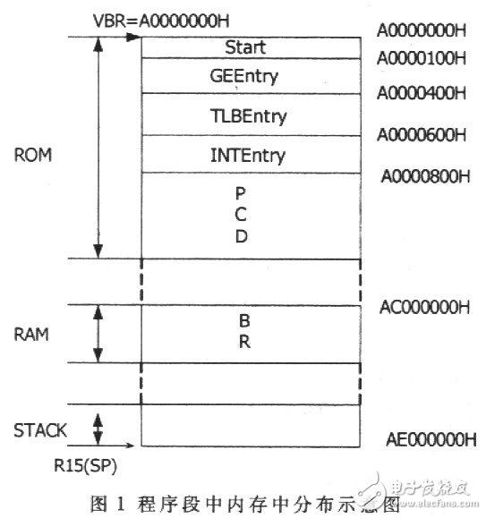
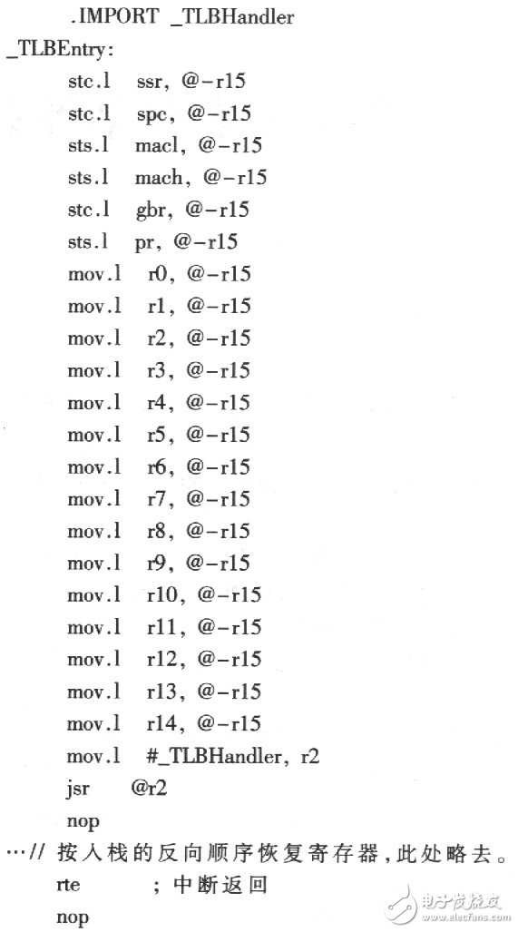
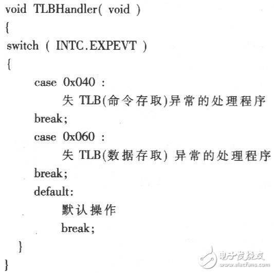
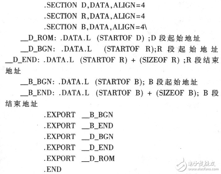
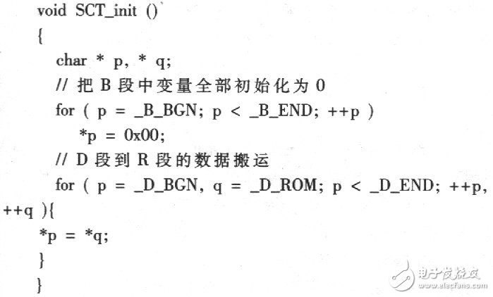
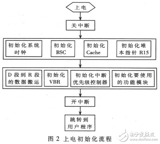
SH-3 is a series of high-end 32-bit RISC architecture microcontrollers from the Renesas SupezH series. It features low power consumption, high performance, integrated MMU, cache, and power management modules. The processing speed is 60 to 260 MIPs. The SH-3 includes the SH7705, SH7708, SH7709, SH7727, and SH7729 microcontrollers, which are widely used in high-end digital devices such as color printers, scanners, and DVD decoders. SH7709S is a representative microcontroller in the SH-3 series. The methods described in this article are verified in the SH7709S system. It mainly introduces three key parts of program design: establishing the interrupt handler structure, initializing the variables assigned initial values ​​in the C program, and powering on the initialization process. The SH-3 interrupt handling method is different from that of a general processor, there is no fixed interrupt vector table, and it is rather flexible. The user can establish the above mentioned memory application for the P09702 only. Through the method introduced in this article, combined with the instruction set of SSDl303, the reader will be able to apply freely to P09702. A program structure that handles abnormal events (Executable Events) as an interrupt vector table. SH-3 divides the anomalies into three categories: Reset, General exception events and General requests. The reset includes power-on, manual, and H-UDI reset. The exceptions include illegal instructions, address errors, etc. Interrupt requests mainly include module interrupts, external interrupts, and so on. Each type of interrupt contains several interrupt sources. Each type of interrupt source corresponds to a different exception code in the INTEVT and IMEVT2 registers. When a reset occurs, the program jumps to address AO000000H. When an exception or interrupt request occurs, the program will jump to the address determined by the vector base register VBR plus a different offset. Different exceptions and interrupt requests correspond to different offsets. The offset corresponding to the anomaly event is 100H. The offset corresponding to the two exceptions generated by the TLB register is 400H, and the offset corresponding to all the interrupt requests is 600H. Initialize the corresponding interrupt handler to the corresponding address. As shown in Figure l. The reset boot program segment (Starl segment) should be placed in the memory of address A00000000H. When VBR=A0000000H, the exception event processing program segment (GEEntry segment) is placed at VBR+100H=A0000100H, and TLB exception processing segment (TLBEntry segment). At VBR+400H=A0000400H, the interrupt request handler segment (INTEntry) is placed at VBR+600H=A0000600H. The space allocated by the system for these several program segments is relatively small. The maximum size is not more than 1 KB. Its main function is to save CPU registers, and then jump to the abnormal code judgment program. The judgment program finds the source of the interrupt and executes the corresponding processing program. The processing of GEEntry, TLBEntry, and INTEntry is similar. The following uses the TLB exception as an example to illustrate this process. When a TLB exception occurs, the program jumps to the VBR+400H address. Enter TLBEntry, first all the CPU registers are saved to the stack (R15 is the stack pointer), after saving, jump to the exception code judgment program TLBHandler, TLBHandlei determine the interrupt source, and execute the corresponding handler. ·SECTIONTLBEntry, CODE, ALIGN=4 ·EXPORT_TLBEntry The following is a TLBHandler program written in C. The program is located in the P section, which is different from the data section in which the TLBEntry section is located (Figure 1). TLBHandler according to INTC.EXPEVT (defined in 7709s.h) to determine what kind of _TLB exception, and jump to the appropriate handler to perform. The compiler divides the compiled C program into the following (see Figure 1): the code segment (P), the constant segment (C), the initialization data segment (D), the initial initialization variable segment (B), and the D segment corresponding to the RAM The data segment (R) and the stack segment (S). The P, C, and D segments are in ROM, and the B, R, and S segments are in RAM. What is saved in the D section is the initial value of the initialized variable at the time of definition, for example, the variable a defined as follows. inTI=l: The compiler actually allocates two blocks of space for initialization variables, the D section in ROM and the R section in RAM. The D section saves the initial value of the variable, and the variable corresponds to the address in the R section. After power-on, the data in segment D needs to be moved to the R segment, which is a very important part of the initialization process of the embedded system. What is saved in the B segment is a variable that has not been assigned an initial value, such as a variable b defined as follows. Intb: You can initialize all the variables in the B segment to 0 at the beginning. The first and last addresses of the D, R, and B sections are given as follows: Then in the initialization process, the initial value in segment D is moved to segment R, and an initial value is assigned to the variable in segment B. The following is a program written in C. The SH-3 power-on initialization process is shown in Figure 2 in the order in which the arrows point. There is no precedence when each part of the same stage is initialized. After power-on, first make the blocking bit BL=1 in the status register SR, prohibit acceptance of exceptions and interrupts, and then start the initialization process. System clock is powered on. The MD0, MD1, MD2 levels and the FRQCR register settings determine the jumper select clock source and bus clock multiplier. FRQCR sets the core and peripheral clock multiplier. The SH-3 address space is generally divided into 7 areas, Area0-Area6, each area takes up 64MB of addresses, Areal is used by the system, and the other 6 areas are used by users. Area0-Area6 (except ATeal) can be connected to ordinary ROM and RAM, each area can be set from 8-32bit bus width and read and write wait cycles, in addition Area2 and Area3 SDRAM interface, Aera5 and Area6 PCMCIA and burstROM interface. The bus width of Aera0 is determined by the levels of pins MD3 and MD4 at power-on, and the bus width in other areas is set by the register in Bus State Controller (BSC). Initialize the BSC to set the memory type, bus width, and read/write wait period for each zone. If SDRAM is connected to Area2 or Area3, initialize the SDRAM controller in BSC. The SH-3 has a built-in cache, which can be set to Write-through (Write to Memory) and Write-back (Write to Cache) using the CCR register. Setting to Write-back mode will significantly increase the speed of the system. There is no dedicated stack pointer SP, instead of R15. After initializing R15, generally do not change the value of R15 in the program. The data handling and initialization VBRs from segment D to segment R are described in detail in Sections 1 and 2. The maskable interrupt of the SH-3 is divided into O~15 priority levels, and only interrupts with priority higher than the SR interrupt mask bits IO~13 can be acknowledged. At the time of initialization, the priority of the interrupt to be used is set. After that, the user is initialized to use the function module. After initialization is completed, the interrupt mask is released and the BL bit in the SR is set to 0. The jump to the user program (usually the main() function in the C language) completes the initialization process. High Voltage Inverter For Car,Car Inverter,Power Inverter,High Voltage Inverter SUZHOU DEVELPOWER ENERGY EQUIPMENT CO.,LTD , https://www.fisoph-power.com