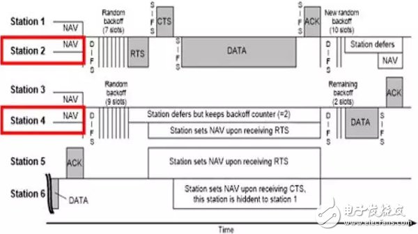
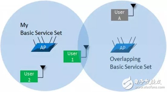
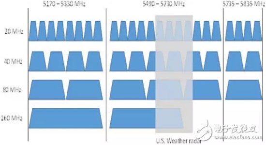
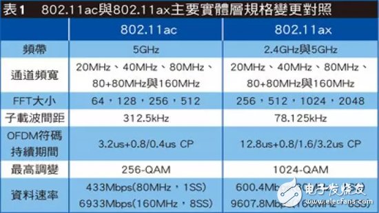
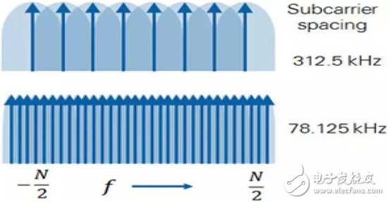
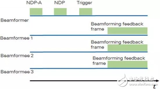
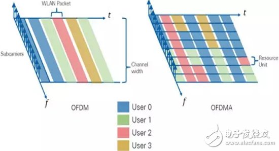
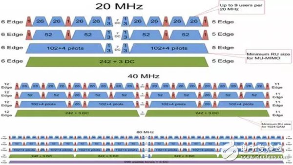
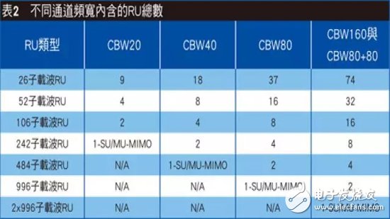
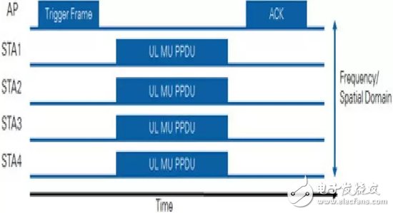
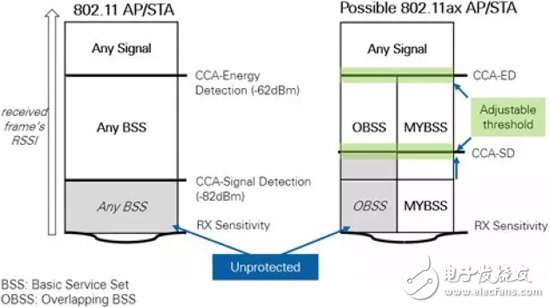
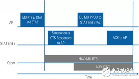
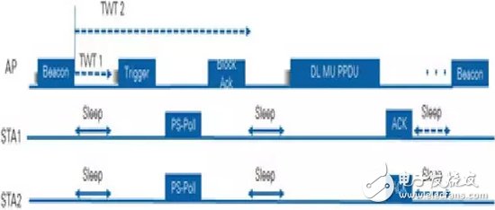
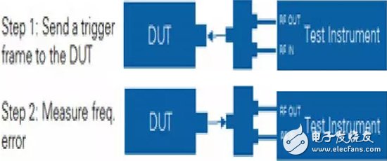
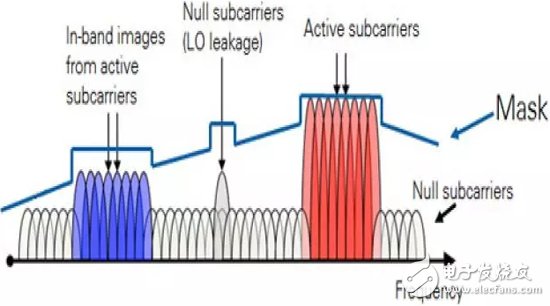
802.11ax, also known as the High-Efficiency Wireless (HEW), aims to achieve a challenging goal: to increase the average transmission rate per user in a user-intensive environment by more than four times. This new standard focuses on the implementation of the mechanism to provide a consistent and stable data stream (average transmission rate) for more users in a crowded environment. This document will lead you through the exploration of new mechanisms that give the 802.11 standard "High Efficiency Wireless Standards" the name. The 802.11ac standard introduced in 2013 not only achieves a link speed of nearly 866 Mbit/s in a single spatial stream, but also provides a wider channel (160 MHz) and a higher modulation order (256-QAM). This technique will achieve theoretical speed values ​​of up to 6.97 Gbit/s as long as 8 spatial streams (standardly specified number of upper limits) are used. Just as Ferrari can only play to the strength of the control track, unless you are in the RF lab, it is difficult to use a 7Gbit/s high-speed wireless network. In the real world, whenever users try to use public Wi-Fi to view e-mails in a busy airport terminal, they tend to frustrate because of the speed of the network. The latest amendment to the IEEE 802.11 wireless LAN standard, 802.11ax, will effectively solve this problem. 802.11ax, also known as the High Efficiency Wireless Standard (HEW), aims to achieve a challenging goal: to increase the average transmission rate per user in a user-intensive environment by more than four times. Strengthen high-density use of contextual network performance The high efficiency wireless standard has the following important features: . Downward compatible with 802.11a/b/g/n/ac. . Increase the average transmission rate per user in high-density locations such as train stations and airports by 4 times. . The data rate and channel width are similar to those of 802.11ac, but can be combined with 1024-QAM to provide new modulation and coding combinations (MCS 10 and 11). . Designated downlink and uplink multi-user jobs are performed through MU-MIMO and Orthogonal Frequency Division Multiple Access (OFDMA) technologies. . Provides four times the size of an OFDM FFT, narrower subcarrier spacing (4x density), and longer symbol time (4x), improving multipath attenuation and outdoor robustness and performance. . Improve traffic and channel access scenarios. . Better power management for longer battery life. High-efficiency wireless standards also meet the needs of the following target applications: . Action Data Discharge: In 2020, Wi-Fi Discharge traffic generated each month will come to 38.1 Exabyte and continue to exceed monthly action flow (30.6EB) estimates. This number is equivalent to moving more than 6,000 Blu-ray movies per minute in these networks. . It has a large number of access points and an environment where high-density users hold heterogeneous devices (airport Wi-Fi, home Wi-Fi). . Outdoor or mixed outdoor environment. Unfavorable high-density transmission of existing Wi-Fi mechanisms The 802.11 communication protocol uses a carrier sense multiple access (CSMA) method. In this mode, the wireless base station (STA) first senses the channel and only transmits when the channel is sensed to be idle. Try to avoid conflicts (Figure 1). If any STA hears that other STAs exist, it will wait for a while before listening again, waiting for the other party to stop transmitting and releasing the channel. When the STA is ready to transmit, the complete packet data will be transmitted. Figure 1. Idle channel evaluation communication protocol Wi-Fi STAs can mediate access to shared media by RTS/CTS packets. The access point (AP) will only send one CTS packet to one STA at a time, and the other party will send the complete frame back to the AP. Next, the STA will wait for the acknowledgement packet (ACK) that the AP uses to inform the packet that it has received correctly. If the STA does not receive the ACK in time, it will assume that the packet conflicts with other transmissions and enters the binary exponential polling period. After the polling count expires, the STA will attempt to access the media and retransmit the packet. This idle channel assessment and collision prevention communication protocol helps to distribute the channel evenly to all participants in the conflicting domain. However, if the number of participants is too large, the allocation efficiency will decrease; multiple AP service areas overlap. It is another reason for the inefficiency of the network. A user (user 1) in FIG. 2 belongs to the basic service group on the left side (BSS, a group of wireless clients associated with the AP). User 1 will compete for media access with other users in his own BSS and then exchange data with his AP. However, the user can still hear traffic from the right overlapping BSS. Figure 2. The media access efficiency caused by the overlap of BSS is not good. In this case, traffic from OBSS triggers User 1's polling process, causing users to wait longer to get transmission opportunities, which in turn drastically lowers their average data transfer rate. The third factor to be considered is the sharing of wider channels. For example, 802.11ac in North America has only one available 160MHz channel, while in Europe there are two (Figure 3). Figure 3. Example of 802.11ax channel configuration in the 5GHz band It is difficult to plan intensive coverage with fewer channels, and this phenomenon forces network administrators to reuse channels in nearby base stations. If you do not pay attention and deliberate power management, users will encounter the same channel interference, in addition to degrading performance, it will also write off the established advantages of the wider channel. When the modulation and coding modes (MCS) 8, 9, 10, and 11 transmit data at the highest data rate, it is particularly prone to encounter low signal-to-noise ratios, and thus it is particularly susceptible to network performance. In addition, in the existing 802.11 network implementation, if the 20MHz channel overlaps with the 80MHz channel, not only will the 80MHz channel be unusable, but the user will also transmit in a narrower channel. In other words, implementing 802.11ac channel sharing in a high-density network will damage the advantages of the 80MHz channel and transmit it over a 20MHz channel. The 802.11ax standard introduces several major changes at the physical layer. However, it is still backward compatible with 802.11a/b/g/n and ac devices. For this reason, 802.11ax STAs can transmit and receive data with legacy STAs, and legacy clients can demodulate and decode 802.11ax packet headers (though not the entire 802.11ax packet) and transmit them over 802.11ax STAs. Polling during the period. Table 1 shows the most important changes to this standard revision and the comparison with the current 802.11ac. Table 1 Please note that the 802.11ax standard will operate in the 2.4 GHz and 5 GHz bands. This specification defines a 4x large FFT and a larger number of subcarriers. However, 802.11ax also covers a major change: reducing the subcarrier spacing to a quarter of the previous 802.11 standard to preserve the existing channel bandwidth (Figure 4). Figure 4. Narrower subcarrier spacing The OFDM symbol duration and the Cyclic Prefix (CP) are also increased by a factor of four while maintaining the same raw link data rate as 802.11ac, while improving the efficiency and robustness of indoor/outdoor and hybrid environments. However, the ax standard specifies a 1024-QAM and a lower cyclic pre-stage ratio in an indoor environment to achieve the highest data rate. 802.11ax will use an explicit beamforming procedure similar to 802.11ac. In this procedure, the beamformer initiates the channel sounding procedure using Null data packets, while the beamforming receiver measures the channel and responds using a beamforming feedback architecture that includes a compressed feedback matrix. The beamformer will use this information to compute the channel matrix H. The beamforming receiver can then use this channel matrix to apply RF energy to each user. Multi-user jobs: MU-MIMO and OFDMA The 802.11ax standard uses two modes of operation, single and multiple users. In the single-user sequence mode, as soon as the wireless STA acquires media access rights, one data transmission and reception operation is performed each time. In multi-user mode, multiple non-AP STA jobs can be synchronized. The standard further divides this pattern into lower-chain and upper-chain multi-users. . The downlink multi-user refers to data that is simultaneously provided by the AP to a plurality of related wireless STAs. The existing 802.11ac already has this feature. . The uplink multi-user involves transferring data from multiple STAs to the AP at the same time. This is a new feature of the 802.11ax standard and does not exist in any of the older Wi-Fi standards. In the multi-user mode of operation, the standard also specifies two ways to multi-task for more users in a particular area: multi-user MIMO (MU-MIMO) and Orthogonal Frequency Division Multiple Access (OFDMA). Regardless of the above, the AP acts as a central controller within the multi-user job, similar to the way LTE base stations control multi-user multitasking. In addition, 802.11ax APs can also combine MU-MIMO and OFDMA operations. In MU-MIMO, 802.11ax devices emulate 802.11ac implementations, using beamforming techniques to synchronize packets to users in different spaces. In other words, the AP will calculate the channel matrix for each user and then direct the synchronization beam to different users, each of which will contain a specific packet for the target user. 802.11ax can transmit up to 8 multi-user MIMO transmissions at a time, much higher than 4 of 802.11ac. In addition, each MU-MIMO transmission has a dedicated MCS and a different number of spatial streams. For example, when using MU-MIMO space multitasking, the AP's role is equivalent to an Ethernet switch, which can reduce domain conflicts from large computer networks to a single port. MU-MIMO uplink steering provides a new feature: the AP will initiate a synchronous uplink transmission from each STA by triggering the frame. When the response of multiple users is consistent with its own packet, the AP applies the channel matrix to the received beam and distinguishes the information contained in each uplink beam. In addition, as shown in FIG. 5, the AP can also initiate uplink multi-user transmission to receive beamforming feedback information from all participating STAs. Figure 5. Beamformer (AP) requires channel information for MU-MIMO operation In the MU-OFMDA section, the 802.11ax standard uses Orthogonal Frequency Division Multiple Access (OFDMA) in the 4G mobile technology field to enable multi-tasking for more users of the same channel bandwidth. The 802.11ax standard is based on the Orthogonal Frequency Division Multiple Access (OFDM) digital modulation architecture used by 802.11ac, which further assigns specific subcarrier sets to individual users. This means that it will use the number of pre-defined subcarriers to divide the existing 802.11 channels (20, 40, 80, and 160 MHz wide) into smaller subchannels. In addition, the 802.11ax standard also emulates modern LTE nouns, referring to the smallest subchannel as a "resource unit" (RU) with at least 26 subcarriers. The AP will determine how to configure the channel according to the traffic demand of multiple users, and continuously assign all available RUs in the downlink. It may configure the entire channel to one user at a time. As with the current 802.11ac, it is also possible to allocate channels to serve multiple users simultaneously (Figure 6). Figure 6. A single user uses channels, different users in the same channel as OFDMA multitasking. In a user-intensive environment, many users often try to use the channel in a way that is not effective. Now, the OFDMA mechanism provides multiple (but exclusive) subchannels for multiple users, which improves each bit. User average transfer rate. Figure 7 illustrates how the 802.11ax system uses different sized RUs for channel multitasking. Note that the smallest channel can accommodate up to 9 users per 20MHz bandwidth. Figure 7. Subdividing Wi-Fi channels using resource units of different sizes Table 2 shows the number of users who can enjoy crossover multitasking access when 802.11ax APs and STAs coordinate MU-OFDMA operations. Table 2 To coordinate uplink MU-MIMO or uplink OFDMA transmissions, the AP transmits a trigger frame to all users. This frame will indicate the number of spatial streams per user and/or the OFDMA configuration (frequency and RU size). In addition, power control information is also included, so that individual users can increase or decrease their transmission power, thereby balancing the power received by the AP from all uplink users, and improving the frame reception of distant nodes. The AP also indicates when all users can start and end the transfer. As shown in Figure 8, the AP transmits a multi-user uplink trigger frame to inform all users when they can start the transmission together, and the duration of the frame to ensure that they can end the transmission at the same time. Once the AP receives the frame of all users, it will return the block ACK to end the job. Figure 8. Coordinating on-line multi-user jobs One of the main design goals of 802.11ax is to provide a single user transfer rate of more than 4 times in a user-intensive environment. To achieve this goal, designers of this standard specify that 802.11ax devices must support both downlink and uplink MU-MIMO operations, MU-OFDMA operations, or both, to accommodate larger simultaneous users. To improve system-level performance and the efficiency of spectrum resource usage in dense deployment scenarios, the 802.11ax standard implements spatial reuse techniques. The STA can identify signals from overlapping basic service groups (BSS) and make media contention and interference management decisions based on this information. When the STA that is actively listening to the media detects the 802.11ax frame, it checks the BSS color bit or the MAC address in the MAC header file. If the detected BSS color in the Protocol Data Unit (PPDU) is the same as the published color of the associated AP, the STA will treat the frame as an Intra-BSS frame. However, if the BSS color of the detected frame is different, the STA will treat the frame as an Inter-BSS frame from the overlapping BSS. After that, the STA considers the media to be busy (BUSY) only when it is necessary for the STA to verify that the framework is from Inter-BSS. However, this period will not exceed the specified frame time. Although the standard still needs to define some mechanisms to ignore the traffic from the overlapping BSS, in practice, it may include increasing the idle channel evaluation signal detection (SD) threshold of the Inter-BSS frame and simultaneously reducing the Intra-BSS. The threshold of traffic (Figure 9). As a result, traffic from neighboring BSSs will not cause unnecessary channel access competition. Figure 9. Idle channel evaluation using color code When 802.11ax STAs use the CCA rules of the color code architecture, they also allow the OBSS signal detection threshold to be adjusted together with the transmission power control. This adjustment is expected to improve system level performance and efficiency of spectrum resources. In addition, 802.11ax STAs can also adjust CCA parameters such as energy detection level and signal detection level. In addition to using CCA to determine whether the current channel is idle or busy, the 802.11 standard also uses Network Configuration Vector (NAV), which maintains future traffic forecasts for STAs to indicate the frame immediately following the current frame. How much time is needed. NAV can be used as virtual carrier sensing to ensure media reservations (such as control framework and RTS/CTS exchanged data and ACK) for frames critical to 802.11 protocol operation. The 802.11 team responsible for developing high-efficiency wireless standards may include multiple NAV fields in the 802.11ax standard, that is, two different NAVs. Having both Intra-BSS NAV and Inter-BSS NAV not only helps STAs predict traffic within their BSS, but also allows them to transmit freely when they know the state of overlapping traffic (Figure 10). Figure 10. Example of MU PPDU exchange and NAV settings The 802.11ax AP can coordinate the use of the Target Wake-up Time (TWT) function with the participating STAs to define a specific time or set of times for individual base stations to access the media. The STA and the AP exchange information, which will include the expected duration of the activity. In this way, the AP can control the contention and overlap between STAs that need to access the media. 802.11ax STAs can use TWT to reduce energy loss and go to sleep before their own TWT. In addition, the AP can additionally set the schedule and provide the TWT value to the STA, so that there is no need for an individual TWT protocol between the two parties. This standard refers to this procedure as "broadcast TWT operations" (Figure 11). Figure 11. Example of target wake-up time broadcast job Due to the introduction of many advanced RF technologies and access control mechanisms, the test and design verification of 802.11ax systems will face six major challenges, namely error vector magnitude (EMV), frequency error, STA power control, access point receiver sensitivity, Intra-band scattering and MIMO testing. More stringent EVM regulations Now 802.11ax will host 1024-QAM related support. In addition, the spacing between subcarriers is only 78.125 kHz. This means that 802.11ax devices require an oscillator with better phase noise performance and an RF front end with better linearity. Test instruments that measure the action of the DUT will require that their EVM noise level be much lower than the DUT. Table 3 lists the EVM levels that an 802.11ax compliant device should conform to. table 3 National Instruments (NaTIonal Instruments, NI)'s WLAN test system combines the RF Vector Signal Transceiver (VST) with the NI WLAN Measurement Suite to support the generation and analysis of 802.11ax signals. The software supports waveforms from binary phase shift (MCS0) to 1024-QAM (MCS10 and MCS11). In addition, NI's VST hardware continuously provides the best EVM level measurement in its class to meet RF characteristics parameter descriptions and production operations. The OFDMA system has a very high magnetic susceptibility to frequency and frequency offset. Therefore, 802.11ax multi-user OFDMA performance requires extremely close frequency synchronization and frequency offset correction. This requirement will ensure that all STAs operate in the configured subchannels and minimize spectrum leakage. In addition, this rigorous timing requirement ensures that all STAs will transmit simultaneously in response to the AP's MU trigger frame. In the case of a 4G LTE system, the base station uses the GPS timing frequency to synchronize all relevant devices. However, 802.11ax AP not only has no advantage of this advantage, but also needs to use the built-in oscillator as a reference for maintenance system synchronization. After that, the STA will extract the offset information from the trigger frame of the AP and adjust the internal frequency and frequency reference accordingly. The frequency and frequency offset test for 802.11ax devices will cover the following tests: . Absolute frequency error: The DUT will transmit the 802.11ax frame, while the test instrument will use the standard reference to measure the frequency and frequency offset. The results will be similar to the current 802.11ac specification, with a limit of approximately ±20 ppm. . Relative frequency error: This will test the ability of STAs not belonging to the AP to participate in uplink multi-user transmissions to link AP frequencies. The test program consists of two steps. First, the test instrument will pass the trigger frame to the DUT. The DUT will adapt according to the frequency and frequency information taken from the trigger frame. The DUT then responds with a frame of corrected frequencies, and the test instrument measures the frequency error of these frames. After the carrier frequency offset and timing compensation are completed, these limits will be closely maintained to less than 350 Hz and ±0.4 microseconds relative to the AP trigger frame (Figure 12). Figure 12, setting of relative frequency error measurement As with the reduced frequency and frequency error requirements, the power received by the AP during uplink multi-user transmission should not be excessively different between multiple users. Therefore, the AP must control the transmission power of each individual STA. The AP can use the trigger frame and include the transmission power information of each STA. Developers can complete this feature by simply using a two-step process similar to the frequency error test. Testing the sensitivities of 802.11ax APs is a challenge, given that APs are used for frequency and frequency references. For this reason, the test instrument needs to lock the AP before transmitting the packet to the AP to facilitate the packet error rate sensitivity test. After transmitting the trigger frame to start the AP, the test instrument adjusts its frequency and frequency with the AP and then responds to the AP DUT by using the packet that is expected to be set (the quantity is predefined). The relative frequency error limit adopted by 802.11ax is quite strict, which is the problem. The test instrument needs to capture extremely accurate frequency and frequency information from the trigger frame transmitted by the AP. The instrument may need to perform this calculation for multiple trigger frames to ensure that frequency and frequency synchronization is smooth. Therefore, this procedure can significantly delay the progress of the test program. To speed up the testing process, one of the possible solutions is to let the AP remit its frequency reference so that the test equipment can lock its own frequency accordingly. This skips the initial synchronization process based on the trigger frame and reduces the time required for the AP receiver sensitivity test. During STA operation in MU-OFDMA mode, they use the RU configuration determined by the AP to upload data to the AP. That is, the STA will only use a portion of the channel. The 802.11ax standard may specify an on-band in-band scatter test to describe and measure the scatter that occurs during the transmitter's use of only part of the frequency configuration (Figure 13). Figure 13. Potential upper-band in-band scattering test mask If 802.11ax devices are tested with up to 8 antennas in a MIMO operation, the results may be quite different from individual and continuous testing of each signal chain. For example, signals from individual antennas can cause negative interference to each other and affect power and EVM performance, which in turn can have a negative and significant impact on transmission rates. Test instruments need to support local oscillator sub-nanosecond synchronization of each signal chain to ensure that phase trimming and MIMO performance of multiple channels are not problematic. NI's test solution is built on NI VST and features patented hardware and software technology to provide flexible, large-scale MIMO settings for up to 8, 16 or even 64 simultaneous channels . 802.11ax can increase the average data rate per user in dense environments by 4 times, and multi-user technology such as MU-MIMO and MU-OFDMA is one of the biggest behind-the-scenes players. This spectrum usage improvement for densely populated environments is expected to promote the adoption of 802.11ax at a speed never seen before. However, the implementation of this feature will bring new challenges to scientists, engineers and technicians responsible for achieving the above engineering miracles. The flexible and modular platform provides high-performance hardware with a compact oscillator and low EVM levels for 1024-QAM measurements with subcarrier spacing density four times higher. WLAN Measurement Suite is at the forefront of the 802.11ax standard, helping developers design, describe, validate and test 802.11ax devices and prepare them for the multi-user revolution.
10-inch tablet devices have greatly surpassed netbooks in terms of entertainment, including reading, games, and audio-visual enjoyment. In other respects, the basic operation of the 10-inch tablet computer built on the touch screen ensures that the application of the tablet computer can be well realized, and its operation performance is closer to that of a smartphone.
1.In appearance, the 10-inches tablet computer looks like a large-screen mobile phone, or more like a separate LCD screen.
2.In terms of hardware configuration, the 10-inches tablet computer has all the hardware devices of a traditional computer, and has its own unique operating system, compatible with a variety of applications, and has a complete set of computer functions.
3.The 10-inches tablet computer is a miniaturized computer. Compared with traditional desktop computers, tablet computers are mobile and flexible. Compared with Laptops, tablets are smaller and more portable
4.The 10-inches tablet is a digital notebook with digital ink function. In daily use, you can use the tablet computer like an ordinary notebook, take notes anytime and anywhere, and leave your own notes in electronic texts and documents.
10 Inches Tablet Pc,Tablet Pc Android,10 Inch Quad Core Tablet,Tablet 10 Inch Jingjiang Gisen Technology Co.,Ltd , https://www.gisentech.com