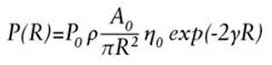
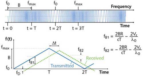
It is reported that the competition between Lidar and other sensor technologies (camera, radar and ultrasound) increases the need for sensor fusion, while also requiring careful selection of photodetectors, light sources and MEMS micromirrors. This article refers to the address: http:// With advances in sensor technology, imaging technology, radar, LiDAR, electronics and artificial intelligence, dozens of advanced driver assistance system (ADAS) functions have been implemented, including collision avoidance, blind spot monitoring, lane departure warning and parking assistance. The operation of such systems is synchronized by sensor fusion to allow fully automated vehicles or unmanned vehicles to detect the surrounding environment and warn the driver of potential road hazards, even taking evasive actions independent of the driver to avoid collisions. Self-driving cars must also be able to distinguish and identify objects in front at high speeds. Using distance determination techniques, these self-driving cars must quickly build 3D maps of roads about 100 meters away and create high-angle resolution images at distances of up to 250 meters. If the driver is not present, the car's artificial intelligence must make the optimal decision. One of the basic methods of this task is to measure the round-trip time (ToF) of the energy pulse from the self-driving car to the target and back to the vehicle. When the speed of the pulse through the air is known, the distance of the reflection point can be calculated. This pulse can be ultrasonic (sonar) or radio (radar) or light (LiDAR). These three ToF technologies, with a higher angular resolution image, LiDAR is the best choice because LiDAR images have smaller diffraction (beam divergence) and better recognition of adjacent objects than radar (see figure 1). Higher angular resolution is especially important for high speed situations that require sufficient time to deal with potential hazards such as head-on collisions. Laser source selection In ToF LiDAR, the laser emits a light pulse of duration Ï„, which activates the internal clock of the timing circuit at the instant of transmission (see Figure 2). When a light pulse reflected from the target reaches the photodetector, an output electrical signal that disables the clock is generated. This electronic measurement round-trip ToF Δt calculates the distance R from the target to the reflection point. If the laser and photodetector are in the same position in reality, the distance R is affected by two factors: c is the velocity of light in a vacuum, and n is the refractive index of the propagation medium (the refractive index in air is close to 1). These two factors affect the distance resolution ΔR: if the diameter of the laser spot is larger than the target size to be resolved, the uncertainty of measuring the spatial width w (w = cÏ„) of Δt and the pulse is δΔt. The first factor is expressed as ΔR = ? cδΔt, and the second factor is expressed as ΔR = ? w = ? cÏ„. If the resolution of the distance measurement is 5 cm, the above relationship indicates that δΔt is about 300 ps and Ï„ is about 300 ps. ToF LiDAR requires photodetectors and electron detectors that utilize small time jitter (mainly contributing to δΔt) and lasers that emit short-term pulses (such as relatively expensive picosecond lasers). In a typical automotive LiDAR system, the laser produces a pulse duration of approximately 4 ns, so a minimum beam divergence angle is required. Figure 1 The beam divergence angle depends on the ratio of the aperture and wavelength of the transmitting antenna (radar) or lens (LiDAR). This ratio is too large for the larger beam divergence angle and smaller angular resolution produced by the radar. As shown, the radar (black) cannot distinguish between the two cars, while the LiDAR (red) can For automotive LiDAR system designers, the most critical thing is to choose the wavelength of the light. However, there are several factors that limit this choice: human eye safety, interaction with the atmosphere, optional lasers, and optional photodetectors. The two most popular wavelengths are 905 nm and 1550 nm. The main advantage of 905 nm light waves is that silicon can absorb photons at this wavelength, while silicon-based photodetectors are typically infrared indium arsenide (InGaAs) that detects 1550 nm light waves. (IR) Photodetectors are cheap. However, 1550 nm is safer for the human eye, allowing the laser to use more energy per pulse – an important factor in the photon budget. Atmospheric attenuation (under all weather conditions), scattering from particles in the air, and reflections from the physical surface of the target are wavelength dependent. But for automotive LiDAR, this is a complex problem due to the many possibilities of weather conditions and reflective surface types. In a realistic environment, since the water absorption at 1550 nm is stronger than that at 905 nm, the light loss at 905 nm is less. Photodetector selection Only a small fraction of the emitted pulses reach the active area of ​​the photodetector. If the atmospheric attenuation does not change with the pulse path, the beam divergence angle of the laser is negligible, the illumination point is smaller than the target, the incident angle is zero, and the reflection is full diffuse reflection (Lambertian), then the peak power P of the pulsed light reception ( R) is: Photodetector selection Where P0 is the peak power of the emitted laser pulse, Ï is the target reflectivity, A0 is the aperture area of ​​the receiver, η0 is the spectral transmission of the probe light, and γ is the atmospheric attenuation coefficient. The above equation shows that as the distance R increases, the received power decreases rapidly. As a reasonable choice of parameters and R = 100 m, the number of photons returned on the active area of ​​the photodetector is close to the typical value (1020 shots), on the order of hundreds to thousands of times. These photons compete with environmental photons that do not carry useful information. The use of narrow-band filters reduces the number of ambient photons that reach the detector, but it cannot be completely eliminated. The environment reduces the dynamic range of detection and increases noise (environmental photon shot noise). It is worth noting that under typical conditions, the ground solar irradiance is in the range of 905 nm to 1550 nm. Figure 2 Detailed explanation of the basic time of flight time (ToF) LiDAR Creating a 360° x 20° 3D map around a car requires raster scanning of single/multiple laser beams, or light coverage of the scene and collection of point cloud data. The former method is called scanning LiDAR, and the latter is Flash area array LiDAR. There are several ways to implement a scanning LiDAR. In the first method, in the case of Velodyne (San Jose, CA), the lidar platform mounted on the roof rotates at 300-900 rpm and pulses from 64 905 nm laser diodes. Each beam has a dedicated avalanche photodiode (APD) detector. A similar approach is to use a rotating polygon mirror to control a single beam of pulses at slightly different tilt angles at different azimuths and downtilt angles. In a harsh and complex driving environment, the moving parts of both designs hide the risk of failure. The second method, which makes scanning LiDAR more compact, is to use a MEMS micromirror to electrically control the beam in the 2D direction. Although there are still some moving parts in the art (the micromirrors also have vibration), the vibration amplitude is small and the frequency is high enough to prevent mechanical resonance between the MEMS micromirror and the automobile. However, the geometry of MEMS micromirrors limits the amplitude of their oscillations, so the LiDAR field of view using MEMS micromirrors is limited, which is a disadvantage of MEMS methods. Despite this, due to the low cost and mature technology of this method, it has earned enough attention. Optical phased array (OPA) technology, the third method of competing scanning LiDAR technology, is popular for its reliable "no moving parts" design. It consists of an array of optical antenna elements that are also illuminated by coherent illumination. Lightwave steering is achieved by independently controlling the phase and amplitude of each component's re-emitted light, which produces an ideal illumination mode, from single to multiple beams. Unfortunately, the optical losses of various small components limit their usable range. The Flash area matrix LiDAR covers the scene with light, even though the illumination area matches the detector field of view. The APD array on the optical focal plane of the probe is the detector. Each APD independently measures the ToF to achieve imaging of the target characteristics by the APD. This is a true "no moving part" approach where the tangential resolution is limited by the pixel size of the 2D detector. However, the main disadvantage of Flash area array LiDAR is the photon budget: once the distance exceeds tens of meters, the number of returned photons is too small to reliably detect. This can be improved if the surface is not covered by light, at the expense of tangential resolution, illuminated with grid-like structured light. Vertical cavity surface emitting lasers (VCSELs) allow them to simultaneously emit thousands of beams in different directions. How to be free from ToF restrictions ToF LiDAR is susceptible to noise due to the detection of electronic return pulses and wide bandwidth weaknesses, while threshold triggering can cause measurement errors Δt. For these reasons, frequency modulated continuous wave (FMCW) LiDAR is an interesting choice. In FMCW LiDAR (or chirped radar), the frequency of the radio wave continuously transmitted by the antenna is modulated, for example, its frequency increases linearly from f0 to fmax with time T, and then linearly decreases from fmax to f0 with time T. If the reflected wave returns from a moving object somewhere back to the transmitting point, its instantaneous frequency will be different from the frequency of the transmitting instant. The difference comes from two aspects: one is the distance from the object, and the other is its relative radial velocity. It can therefore be determined by electronically measuring the frequency difference and calculating the distance and velocity of the object (see Figure 3). Figure 3 In the chirped radar, by measuring fB1 and fB2 electronically, the distance of the reflected object and its radial velocity can be determined. Inspired by the chirped radar, the FMCW LiDAR can approach the object being measured in different ways. In the simplest design, "å•å•¾chirp" (wideband chirp) modulation can be performed against the beam intensity of a bright target. This frequency follows the same rules as the carrier frequency of the FMCW radar (eg Doppler effect). The reflected light is detected by the photodetector and then its modulation frequency is restored. The output is amplified and mixed with the local oscillator to allow for a change in the measured frequency while calculating the distance and speed of the target. But FMCW LiDAR also has its limitations. It requires more computing power than ToF LiDAR. Therefore, FMCW LiDAR is slower when generating a full 3D environment view. In addition, the accuracy of the measurement is very sensitive to the linearity of the skew line. Although designing a fully functional LiDAR system is challenging, these challenges can be overcome. As the research progresses, we are getting closer and closer to the era when most cars can be fully automated after they are assembled. Somke Machine Fog Smoke Machine Somke Machine Series,Smoke Machine,Wedding Smoke Machine,Smoke Machine Party Guangzhou Chengwen Photoelectric Technology co.,ltd , https://www.cwleddisplay.com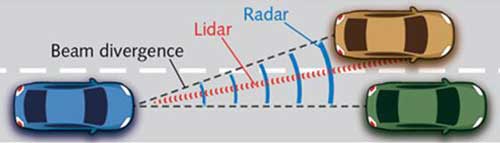

Feature:
* DURABLE MATERIAL: It is made of top grade aluminum alloy, built-in fan for heat dissipation, stable and lightweight. Look upscale and durable for long time.
* BEAUTIFUL COLOR SHOW: It can choose single colors or color combinations. It will be great enjoyment to see the colorful light projected to the ceiling, wall and floor,etc.
* SUIT FOR VARIOUS OCCASION: Suit for various parties, birthday, dance, holiday, celebrations, Karaoke, family or friend home celebration. The laser light can be used in home, disco, living room, bar, club, or anywhere needed.
* EASY OPERATION: The light will enter sound activated mode, which makes the lights blink according to the beat of the music or sound. Adjustable motion speed.
* CREAT ATMOSPHERE EVERYWHERE: This laser light is mini size with tripod, portable and convenient for carry. You can place it everywhere.
Our company have 13 years experience of LED Display and Stage Lights , our company mainly produce Indoor Rental LED Display, Outdoor Rental LED Display, Transparent LED Display,Indoor Fixed Indoor LED Display, Outdoor Fixed LED Display, Poster LED Display , Dance LED Display ... In additional, we also produce stage lights, such as beam lights Series, moving head lights Series, LED Par Light Series and son on..