It’s not a good idea to do the analog filter design.
What if there's a tool that helps you refine your design choices before running any simulation? The Analog Filter Design Wizard is exactly that kind of powerful and practical tool, specifically designed for real-world operational amplifier applications.
This smart tool eliminates the need for guesswork when it comes to filter selection. It allows you to quickly design low-pass, high-pass, or band-pass filters with the exact specifications you need—significantly reducing setup time (see Figure 1). Plus, it offers in-depth analysis of both theoretical and real-world performance, giving you confidence in your final design.
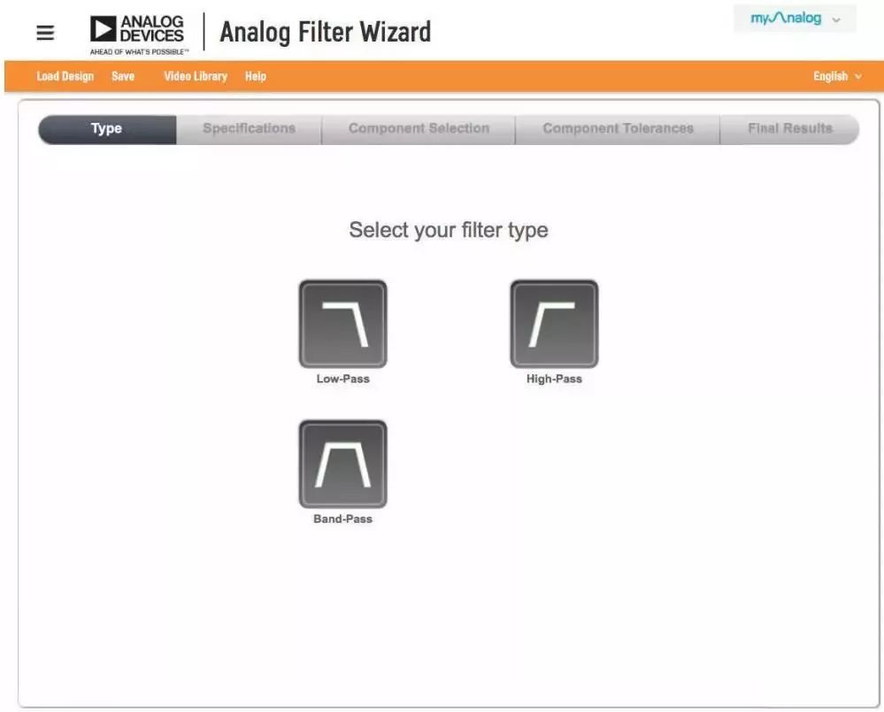
**Figure 1. Filter type**
So, how does the Filter Design Wizard actually work? Are its recommendations only based on passband and stopband definitions?
**No, it goes much further.** The wizard takes you through the entire design process—from defining filter characteristics to analyzing the response. As shown in Figure 2, you can choose from various filter types like Butterworth, Chebyshev, or Bessel, which determine how the signal transitions between the passband and stopband. You can also decide between a less-level circuit topology or a more optimized one, depending on your needs.
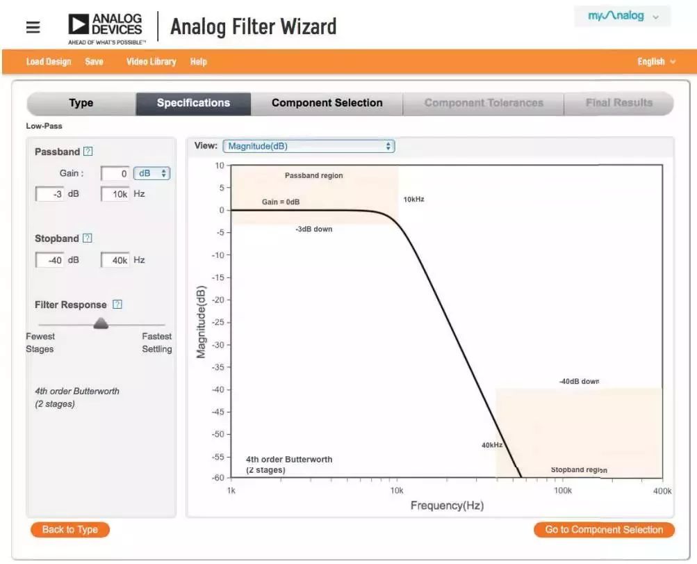
**Figure 2. Defining properties in the amplitude view**
The Analog Filter Wizard provides multiple views—such as amplitude, phase, step response, power, and noise—to help you evaluate how changes in parameters affect the overall performance. For example, the amplitude and phase views (Figures 2 and 3) allow you to see how the signal behaves in terms of both magnitude and timing.
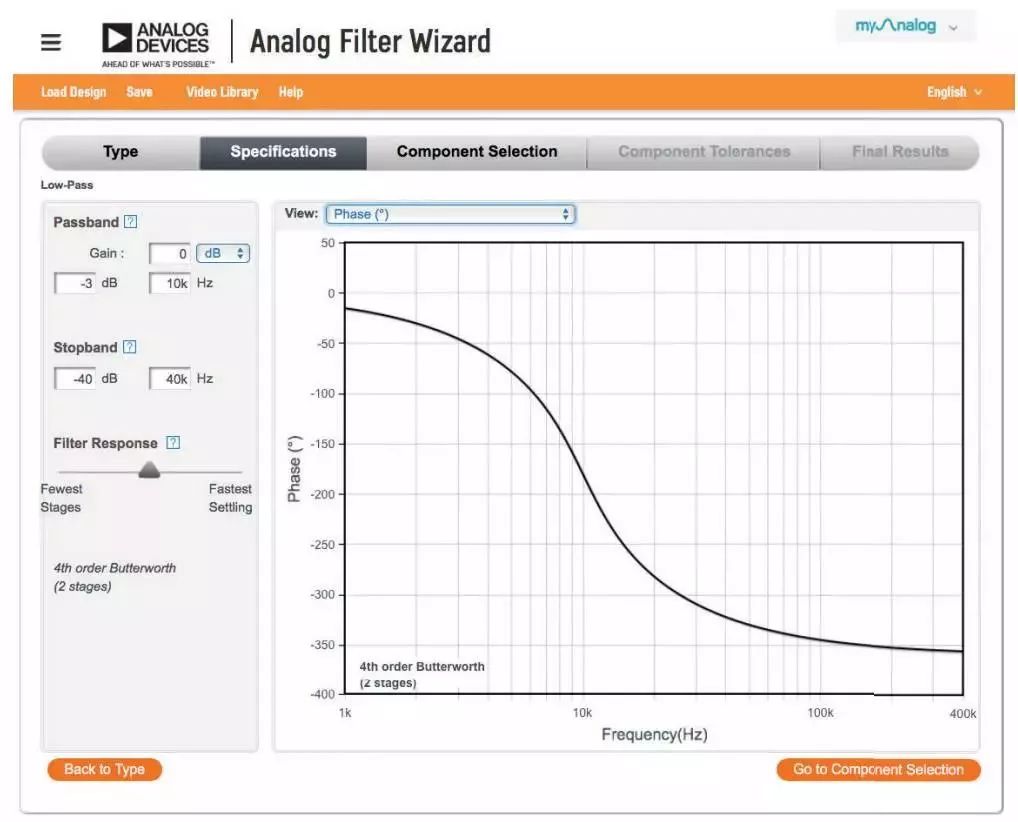
**Figure 3. Phase view**
The level view (Figure 4) gives you a clear overview of the op-amp filter’s key parameters, making it easier to assess and grade the filter’s performance.
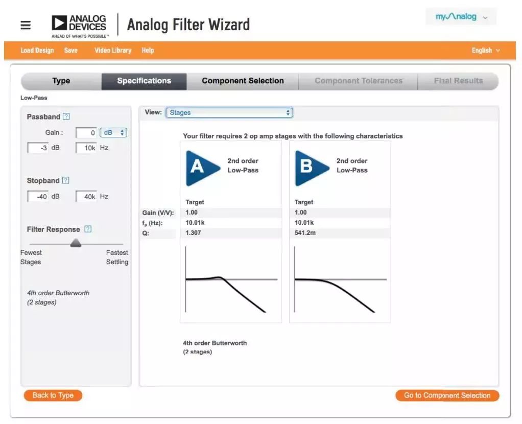
**Figure 4. Filter level view**
Overshoot and ringing in the signal waveform can be analyzed using the step response view (Figure 5), which shows how the filter reacts to sudden input changes.
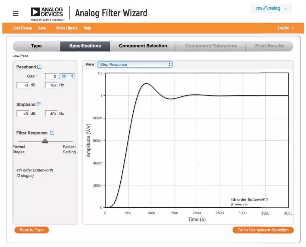
**Figure 5. Step response of the filter**
Once the theoretical characteristics are set, the next step is circuit design (Figure 6). At this stage, the Analog Filter Wizard provides component recommendations based on your chosen optimization criteria, such as power consumption, noise levels, or voltage range. You can either use the suggested components or make your own selections.
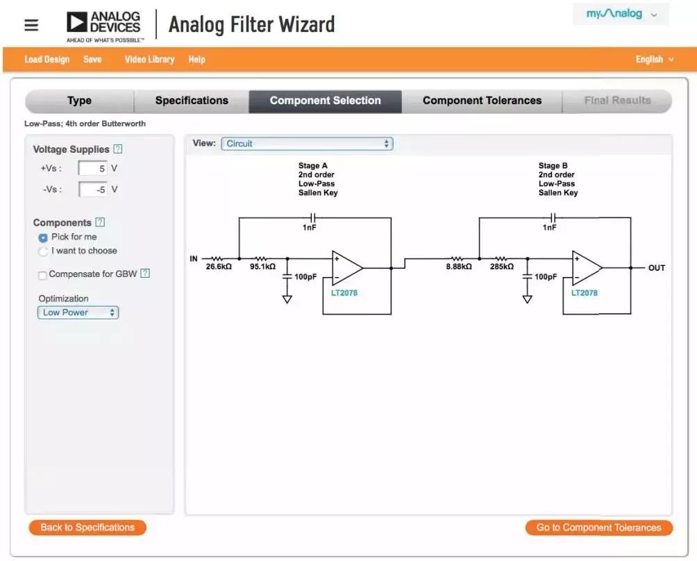
**Figure 6. Component selection**
Even though the wizard suggests the best device for your application, sometimes it may be difficult or impractical to find an exact match. That’s where the component tolerance function comes in handy (Figure 7). You can adjust resistor and capacitor tolerances and see how those changes impact the filter’s performance.

**Figure 7. Defining component tolerances**
Finally, Figure 8 shows the complete circuit design, ready for simulation or prototyping, using the appropriate amplifier for your application.
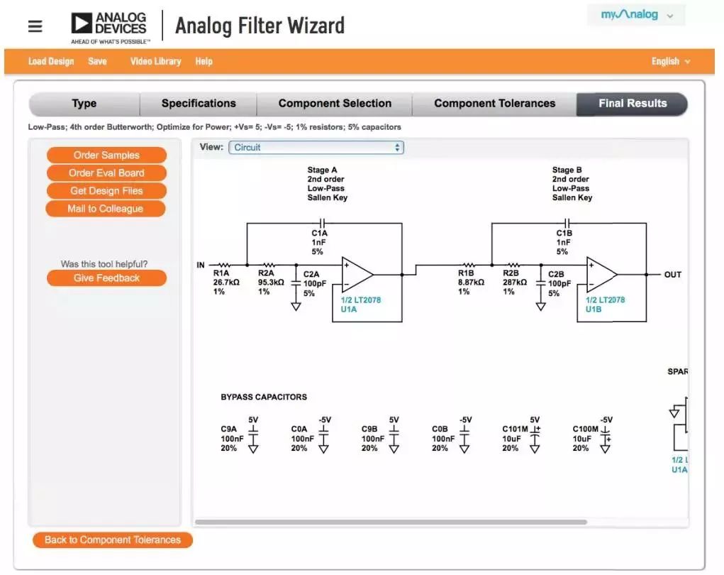
**Figure 8. Final circuit**
The Analog Filter Wizard is not just a tool—it’s a comprehensive solution that guides you through every stage of the design process. From defining filter characteristics to adjusting component tolerances, it ensures that your design is optimized at every step. This level of detail and flexibility makes it easier to achieve the best results with fewer iterations, saving time and effort while improving accuracy.
Water Dispenser,Electric Bottled Drinking Water Dispenser,Portable Cold Water Dispenser,Portable Water Dispenser Pump
Shenzhen Ruidian Technology CO., Ltd , https://www.wisonen.com