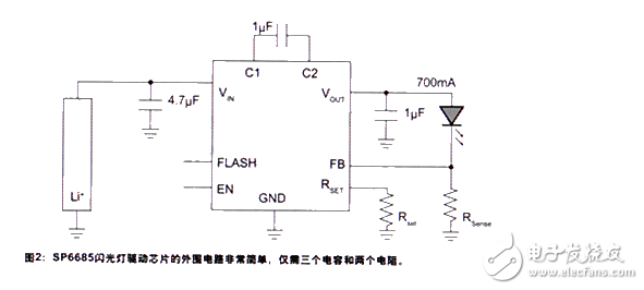
Every year, hundreds of mobile phones are added to the market. The basic functions of these phones are the same, that is, communication. The peripheral design of the mobile phone is the main way to increase the additional functions of the mobile phone, increase the selling point of the mobile phone and new profit points. The difference between different mobile phones mainly resides in peripheral functions such as appearance, screen color brightness, multimedia functions, Bluetooth, camera functions, and the like. The integrated camera function of mobile phones is an inevitable trend in the design of mobile phones nowadays, and the pixels of mobile phone cameras are also getting higher and higher. For better image quality, the flash function of mobile phone cameras has become more and more important. Current mobile phone cameras mainly use LED flash. The LED for the flash lamp requires only 3.5 to 4.5 V DC voltage and 120 to 250 mA current to emit high brightness light of 2000 to 7500 mcd. LED low-voltage flash circuit is simple, efficient, power-saving, low cost, small PCB area, especially suitable for mobile phones, digital cameras and handheld devices, and is very popular in the market of handheld imaging products. According to the output characteristics of the driving circuit, the driving circuit of the LED flash can be divided into a constant voltage type and a constant current type; according to the working principle of the circuit, it can be divided into a boosting circuit and a charge pump circuit. LEDs are current-driven devices whose brightness is proportional to current. In a constant voltage type drive circuit, there is often a resistor in series with the LED to determine the voltage that is required to be supplied to the LED to produce the desired forward current. This approach has the disadvantage that any change in the forward voltage of the LED will result in a change in the LED current, so that the current flowing through the LED cannot be guaranteed to be equal to the preset value, and the brightness of the LED cannot be guaranteed to be constant. In the constant current type driving circuit, the current flowing through the LED is made constant by detecting the voltage of the resistor connected in series with the LED. This approach eliminates current variations caused by forward voltage variations and therefore produces a fixed LED brightness. Since the working range of the battery voltage of the mobile phone is generally 3.6V to 4.2V, and the forward voltage of the LED is generally 3V to 4V, when the low voltage input and the high voltage output are stored, the boost circuit must be used to drive the voltage to drive. LED. Flash lamps are generally boosted in two ways, one is a booster circuit that uses an inductor as an energy storage component, and the other is a charge pump that uses a capacitor as an energy storage component. The booster circuit uses an inductor as the energy storage component, which has the advantage of relatively high efficiency. Figure 1 shows the schematic of the boost circuit. The LED flash driver controllers on the market now integrate control circuitry and boost switching transistors, but the inductors and Schottky diodes for freewheeling are external, which adds to the complexity, cost and PCB area of ​​the circuit. In addition, since the flash drive circuit, the LED, the display screen, and the mobile phone antenna are generally located at the upper end of the mobile phone, and the RF circuit of the mobile phone is very close, it is also an important problem to effectively prevent the EMI interference of the drive circuit inductance. The charge pump uses a capacitor as the energy storage component, and the charge pump does not require an external inductor, so there is no problem of electromagnetic interference. In addition, the entire solution occupies a smaller PCB area, but is relatively inefficient. Since the flash working time is very short, the duration is generally 100 to 300 ms, so the effect of efficiency on the battery life is not too great. Sipex's charge pump operating mode based flash driver chip, SP6686, SP6685 and SP7685 support flash currents of 400mA, 700mA and 1.2A respectively. Because of their switching frequency of up to 2.4MHz, the input and output capacitors and charge pump capacitors can be chosen to be lower than their products. All three products are foot-to-foot compatible, only the maximum current is different. The characteristics and applications of these products are discussed below using SP6685 as an example. Figure 2 shows the application circuit diagram of SP6685. The peripheral circuitry of the Sipex flash driver family is very simple, requiring only three capacitors and two resistors, with Rsense and RSET to set the LED current for flash mode and constant light mode. Mc4 Connector Extension Cable,Solar Panel Wire 10 Awg,Pv Extension Wire,Optical Ground Wire Sowell Electric CO., LTD. , https://www.sowellsolar.com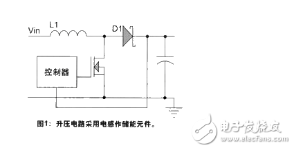
Foreword