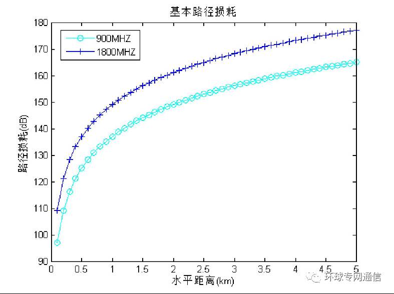
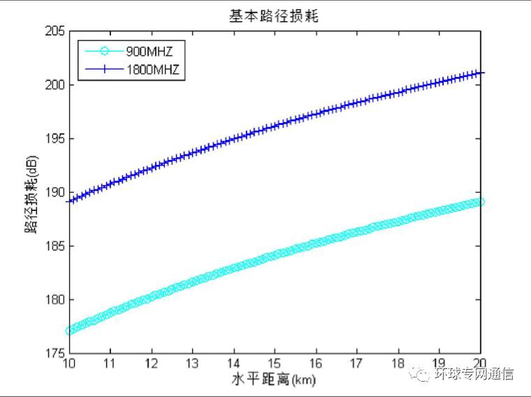
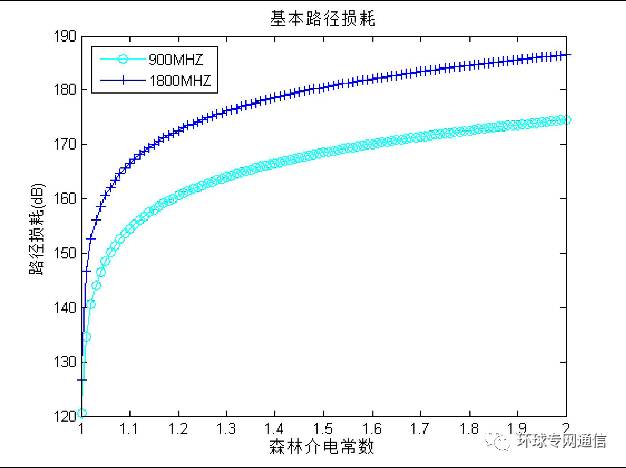
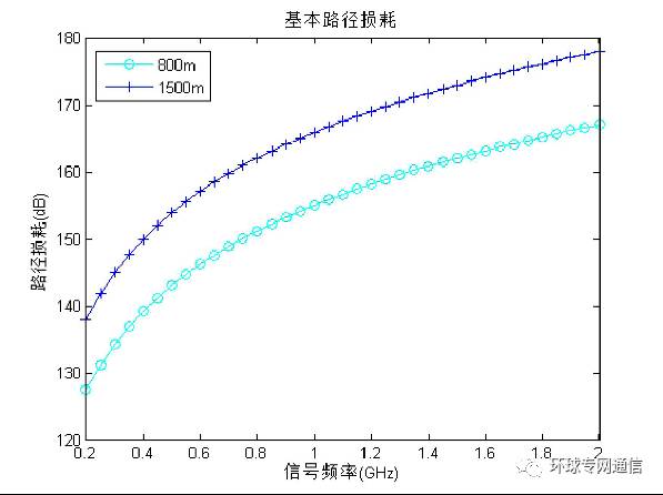
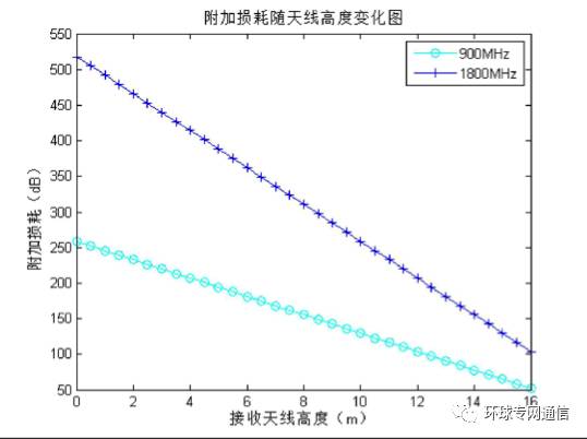
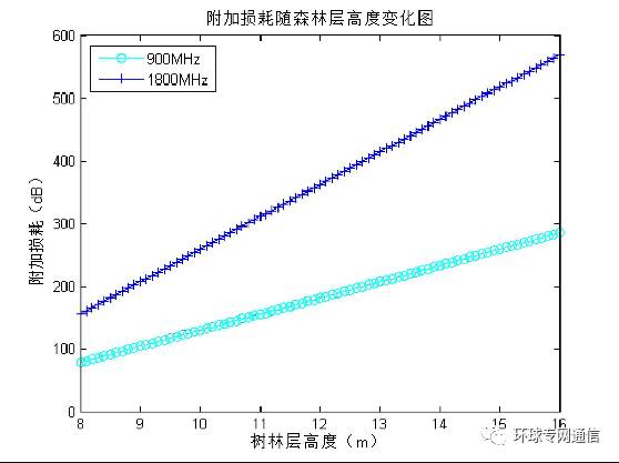
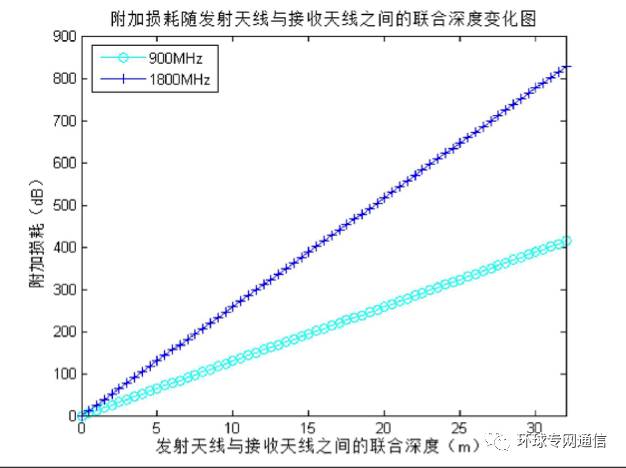
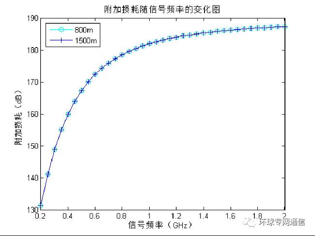
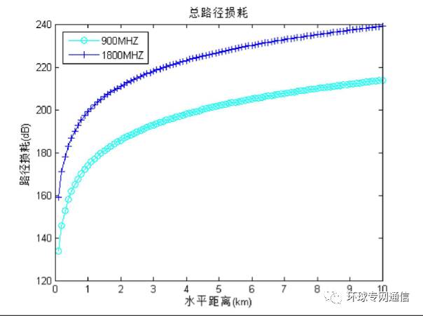
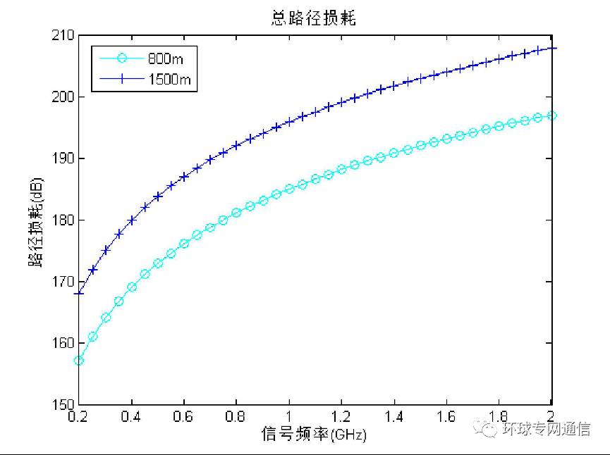
China is generally a country with a lack of forests and greens and fragile ecology. It is a country with significant climate impacts and frequent forest fires. Forest fires are sudden, destructive, and dangerous. They are one of the most frequent, most difficult, and most serious natural disasters in the world. Natural disasters such as burning, burning ash, smoking, wild donkeys, hunting, burning paper on the graves, car leaks, etc., such as fire behavior and lightning strikes, can cause forest fires. From 2001 to 2015, there were 67,694 general fires in China, 48,235 large, 208 major, and 34 large, with a total of 116,171, with a total area of ​​3,522,582 hectares and a damage area of ​​1,429,477 hectares. It poses serious risks and consequences. Forest protection and legislation must be given high priority, and forest fire prevention is important in prevention. Forest fire prevention implements the principle of “prevention first, actively eliminatingâ€. Preventing work is a prerequisite for preventing forest fires, and establishing a sound forest monitoring communication system is the main measure for prevention. To this end, it is necessary to understand the propagation characteristics of forest radio waves, which is the basis for the development of forest monitoring communications. In areas with large numbers of buildings, images of trees and vegetation on communication can often be ignored. However, trees and vegetation in forests are important factors in the propagation of image radio waves. The occlusion, scattering and absorption caused by trees and vegetation can cause large path losses. In the tropical forest environment of the Second Pacific World War II, wireless communication devices generally failed. Later, people learned through experiments that the harsh climate and complex electromagnetic environment in tropical and subtropical forest areas are the main reasons for interference in wireless communications. With the rapid development of mobile communications, people's requirements for the communication environment are becoming more and more strict, and it is necessary to ensure a certain communication quality from the urban environment to the forest environment. As far as the current status quo is concerned, the urban population density is relatively large, and the capacity of mobile communication is relatively saturated. Mobile communication technologies have been rapidly popularized in suburbs and rural areas, and even in the forest. The forest environment often attracts a large number of adventure enthusiasts. Moreover, due to the consideration of military warfare, the forest is also a place that cannot be ignored. However, the forest is often filled with many uncertain factors, such as weather, humidity, vegetation coverage, and sparseness of trees. The propagation of radio waves in the complex environment of forests is highly uncertain and transmission can be greatly disturbed. In the forest environment, we mainly study the effects of trees, vegetation and other factors on electromagnetic wave propagation. The theoretical research and experimental testing of forest communication began in the 1950s. In order to solve the communication problem of the Vietnam War, the United States invested a lot of manpower and resources to carry out research on forest communication, and conducted a field survey and experiment for 5 years in Thailand. . At the same time, China has also conducted experiments for three years in native forest areas. From the 1970s to the 1980s, the experimental frequency band was gradually extended from the HF/VHF band to the UHF band, indicating that research that was originally limited to terrestrial communication problems has been extended to address integrated communications including battlefield reconnaissance, electronic countermeasures, and satellite networking in forest environments. field. The research on forest communication is put forward in practical applications. Therefore, the research is basically carried out simultaneously from both theoretical and experimental aspects. Theoretical research mainly focuses on the main mode of radio wave propagation in forest communication—the propagation characteristics and propagation mechanism of side waves; the experimental research is mainly based on measuring the propagation path loss and antenna effect of the actual jungle environment. The most classic Tamir forest model in the study of path loss in forests, the forest is equivalent to a layer of lossy medium. Based on the received field values ​​obtained by Tamir, the correctness of the model is simulated by simulation. Prove and explore some basic parameters, such as forest height, propagation distance, receiving antenna height, and the frequency of the transmitted signal, which have an impact on the path loss value of the wave propagation in the forest. 1 basic path loss 1.1 Path loss and propagation distance Here, the refractive index of the ground and the refractive index of the forest medium are set to N2=10+i, n2=1.03+0.03i, respectively. For the sake of simplicity, the polarization of the transmitting antenna selects vertical polarization. Figure 1 and Figure 2 show the basic path loss of electromagnetic waves during propagation in the case of short-range propagation and long-distance propagation, respectively. Figure 1 Basic path loss versus distance curve when the propagation distance is short Figure 2 Basic path loss versus distance curve when the propagation distance is long It can be seen from Fig. 1 and Fig. 2 that the basic path loss increases with the increase of the transmission distance. When the propagation distance is short, the value of the basic path loss changes exponentially with the propagation distance, and when the propagation distance is long, The value of the basic path loss varies linearly with the propagation distance. In addition, by comparing the two curves, the higher the frequency of the transmitted signal, the larger the value of the basic path loss. 1.2 Path loss and dielectric constant When the distance between the transmitting and receiving antennas is set to 1.5 km and the conductivity of the forest medium is set to 0.1 mS/m, the basic path loss suffered by the radio waves during the propagation can be obtained, as shown in FIG. Figure 3 Basic path loss curve with forest dielectric constant It can be seen from Fig. 3 that in the process of electromagnetic wave propagation, the basic path loss increases exponentially with the increase of forest dielectric constant. When the value of the forest dielectric constant is small, the parameter has a great influence on the basic path loss. When the value of the forest dielectric constant increases gradually, the effect of the parameter on the basic path loss gradually becomes smaller, and the basic path loss is gradually reduced. The value of the growth is slow. 1.3 Path loss and signal frequency The dielectric constant of the forest layer is set to 1.3, and when the conductivity is set to 1 mS/m, the basic path loss experienced by the radio waves of different frequencies during the propagation can be obtained, as shown in Fig. 4. Figure 4 Basic path loss curve with signal frequency It can be seen from Fig. 4 that as the frequency of the transmitted signal increases, the value of the basic path loss of the electromagnetic wave during the propagation also gradually increases. Moreover, the basic path loss between the transmitting and receiving antennas of 1500 meters apart is always larger than the basic path loss between the transmitting and receiving antennas of 800 meters apart, which is consistent with the above analysis. 2 additional loss The additional loss is determined by the wavelength of the transmitted signal, the joint depth s between the transmitting and receiving antennas, and the refractive index n of the forest medium. Set the height of the transmitting antenna to 12 meters and the height of the forest layer to 16 meters. The other parameters are unchanged and the following image is obtained. 2.1 additional loss and receiving antenna height Figure 5 Additional loss with receiving antenna height curve It can be seen from Fig. 5 that as the frequency of the transmitted signal increases, the value of the additional loss becomes larger. Further analysis, we can find that as the height of the receiving antenna increases, the value of the additional loss gradually decreases and exhibits a linear relationship. 2.2 Additional loss and height of the forest layer When the height of the transmitting antenna is 6 meters and the height of the receiving antenna is 4 meters. When the other parameters are the same, changing the height of the forest layer can obtain the additional loss curve with the height of the forest layer, as shown in the following figure. Figure 6 Additional loss with forest layer height curve It can be seen from Fig. 6 that the additional loss increases with the increase of the height of the forest medium layer, and almost changes linearly. The additional loss of the higher frequency transmitted signal is relatively faster, and for the same height of the forest layer, the additional loss value of the 1800 MHz signal is greater than the 900 MHz signal. 2.3 Additional loss and joint depth Through theoretical analysis, it can be obtained that changing the height of the transmitting antenna or the receiving antenna and the height of the forest layer, the actual change is to change the value of the joint depth s between the transmitting antenna and the receiving antenna, which is the main factor affecting the additional loss. factor. Therefore, what is discussed next is to change the effect of the joint depth s between the transmitting and receiving antennas on the additional loss. When the forest height is 16 meters and the other parameters are the same, changing the joint depth s between the transmitting antenna and the receiving antenna can obtain the additional loss as a function of the joint depth s between the transmitting antenna and the receiving antenna, as shown in the following figure. Figure 7 Additional loss versus joint depth curve As can be seen from Fig. 7, as the value of the joint depth between the transmitting antenna and the receiving antenna in the forest becomes larger, the value of the additional loss also increases linearly. When the joint depth between the transmitting antenna and the receiving antenna is 0 meters, it means that the transmitting antenna and the receiving antenna are both erected at a height of 16 meters, and the value of the additional loss is 0 dB. When the joint depth between the transmitting antenna and the receiving antenna is 32 meters, the value of the additional loss is very large, and the signal is seriously attenuated during propagation. 2.4 Additional loss and signal frequency When the height of the transmitting antenna is 5 meters, the height of the receiving antenna is 5 meters, the height of the forest layer is 15 meters, the dielectric constant of the forest is set to 1.3, and the conductivity is set to 1 mS/m, the frequency of the transmitted signal can be changed. The additional loss varies with the frequency of the transmitted signal, as shown in Figure 8. Figure 8 Additional loss vs. transmitted signal frequency It can be seen from Fig. 8 that the two curves of the transmitting and receiving antennas are 800 m and 1500 m apart, which indicates that the additional loss is independent of the distance between the transmitting and receiving antennas. As the frequency of the transmitted signal increases, the value of the additional loss gradually increases, but when the frequency is increased to 1 GHz, the value of the additional loss changes very slowly, and the influence of the frequency of the transmitted signal gradually decreases. 3 total path loss It can be known from the above analysis that the path loss of electromagnetic waves is mainly composed of two parts, one is the loss L0 in the absence of the ground, and the other is the additional loss Ls in the presence of the ground and the transmitting and receiving antennas are located in the forest, and the total path The loss is the sum of the two, that is, L = L0 + Ls. When the height of the forest layer is 10 meters, the height of the transmitting antenna and the receiving antenna are both 5 meters, the forest dielectric constant is 1.3, and the conductivity is 1 mS/m, the total path loss is shown in Fig. 9. 3.1 Total path loss and propagation distance Figure 9 Total path loss curve with transceiver antenna distance It can be seen from Fig. 9 that the transmission signal with a higher frequency suffers a more serious attenuation during the propagation process, and the value of the path loss is larger. The total path loss value changes exponentially with the increase of the horizontal distance. When the value of the horizontal distance is small, the value of the path loss increases faster, and when the value of the horizontal distance is larger, the value of the path loss increases. The trend tends to be flat. 3.2 Total path loss and signal frequency When the height of the forest layer is 10 meters, the height of the transmitting antenna and the receiving antenna are both 5 meters, the dielectric constant of the forest is 1.3, and the conductivity is 1 mS/m, consider the different distance between the transmitting antenna and the receiving antenna to obtain the total path. The variation of the loss with the frequency of the transmitted signal is shown in Figure 10. Figure 10 Total path loss as a function of the frequency of the transmitted signal It can be seen from Fig. 10 that the variation range of the signal frequency is set from 0.2 GHz to 2 GHz. As the frequency of the transmitted signal increases, the total path loss value of the radio wave during propagation also increases. For the two curves in Figure 10, when the transmitting and receiving antennas are separated by 800 meters, the path loss value is always smaller than the distance between the transmitting and receiving antennas of 1500 meters. Therefore, when we research and develop the forest monitoring communication system, we should select the appropriate signal frequency and the height of the transmitting and receiving antenna according to the dielectric constant of the specific wave propagation characteristics of the forest and the height of the forest layer to meet the communication distance to the basic path loss and additional loss. Technical requirements with total path loss. Suizhou simi intelligent technology development co., LTD , https://www.msmvape.com