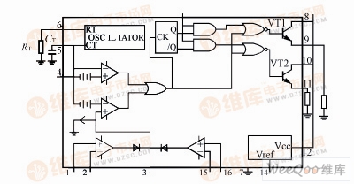
This power control circuit uses the TL494 chip produced by MOTOLOLA. TL494 box circuit diagram
A through-bore slip ring is an electrical device that allows current to pass between two points in a rotating assembly without a physical connection. There is no break in the circuit. This is accomplished by passing the current through a rotating brush that contacts a stationary metal ring. The metal ring is mounted on the shaft of the assembly and provides a continuous path for the current.
It is an integrated circuit component that consists of two conducting rings that are separated by a gap or spacer. When the rings are brought into contact, current can flow between them and produce a rotational motion. Slip rings are used in various applications where high efficiency and low power consumption are essential, such as communication systems, motor control systems, and energy harvesting devices.
The through-bore design allows for rotation of the assembly while transmitting power or data. They are often used in applications where there is a need to rotate an object while keeping a power or data connection open, such as on a wind turbine or radar antenna.
The Oubaibo's through-bore slip ring is a newly designed product that has many advantages over other products on the market. It is small and lightweight, making it easy to install and use. The through-bore design also allows for a high degree of flexibility, making it ideal for use in difficult or tight spaces. Additionally, the Oubaibo through-bore slip ring is very efficient, providing a high degree of power transfer with minimal loss.
Through-Bore Slip Ring,Slip Ring Connector,Power Slip Ring,Slip Ring Assembly Dongguan Oubaibo Technology Co., Ltd. , https://www.sliprobs.com
The TL494 is a fixed frequency PWM control circuit suitable for designing all typical (single-ended or double-ended) switching power supplies. The main features are as follows:
1) Input power supply DC7 ~ 40V, can be used as an input power supply without an unregulated power supply, thus simplifying the auxiliary power supply. When the two power tubes of the last stage of TL494 operate in the range of 7~40V, the maximum output current can reach 250mA. Therefore, its load capacity is strong, it can work in push-pull mode, and two outputs can be operated in parallel, and can be directly driven at low power.
2) There is a 5V reference voltage inside, which is easy to use. When the reference voltage is short-circuited, it has sagging protection characteristics.
3) There is a pair of operational amplifiers inside, which can be used as feedback amplifier and protection. The control is very convenient.
4) In the high-frequency switching power supply, the output square wave must be symmetrical. In other applications, the square wave is artificially asymmetrical, that is, the duty cycle of the square wave needs to be controlled, and the fourth leg of the TL494 (dead time control) The control of the terminal can adjust the duty cycle and can also be used for output soft start protection.
5) You can select single-ended, parallel and alternate three methods of output.
It can be seen from Fig. 1 that the pins 1 and 2 of the TL494 chip are the input of the operational amplifier, the circuit is used for voltage feedback, the pin 1 is the feedback input, and the pin 2 is divided by the internal reference voltage 5V through the resistor on the pin 14 as a Bench 1 comparison benchmark. Pin 3 is the compensation correction, which is the input of the PWM comparator. The access resistor and capacitor can suppress the oscillation. Pin 4 is the dead zone control. The higher the voltage applied to pin 4, the larger the dead zone width. When it is grounded, the dead zone is zero, that is, full output. When it is connected to 5V, the dead zone is the largest and there is no output pulse. With this feature, a capacitor in the foot 4 and the foot 14 can achieve the purpose of output soft start, and can also be used for short circuit protection. Pins 5 and 6 are the grounding capacitance of the oscillator, and the resistance of this circuit oscillator is 50 kHz. Pin 14 is the internal reference voltage +5V. Pins 15 and 16 are the input of another operational amplifier. This circuit is used for current feedback and for current protection. When not in use, pins 15 and 16 can be shorted to ground.