Universal power module schematic diagram common fault handling method
The Kaiyu brand intelligent switching power supply, also known as the universal power module, is a versatile solution designed for replacing switching power supplies in 14-inch to 34-inch color TVs, VCDs, DVDs, and satellite receivers. During repairs, only the rectification filter, spike absorption circuit, and secondary rectification section of the original unit need to be retained. This significantly enhances repair efficiency and simplifies the maintenance process.
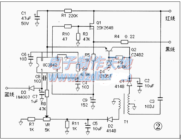
To better understand the internal workings of the power module, the author disassembled it and created a schematic diagram. From the diagram, it's clear that the module follows a design similar to the switching power supply found in color displays. It uses a typical UC3842 + FET configuration, with the exception that the blue wire is not connected. In this setup, the error signal is sampled from the primary side. The UC3842 is a highly efficient PWM controller, widely used due to its simple structure and excellent performance. Since it has only one output, it is typically used in single-output switching power supplies.
**Debugging Method:**
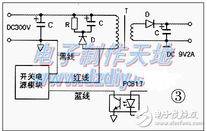
Connect the module to the circuit as shown in Figure 3. The red wire should be connected to the C-pole position of the original switch transistor, the black wire to ground, and the blue wire to pin 4 of the optocoupler for remote control standby (if the original machine uses step-down standby, a 5kΩ–10kΩ adjustable resistor should be added in series). Disconnect all loads in the original circuit and connect a 60W–100W bulb to the output as a dummy load. After checking the power supply, use a multimeter to monitor the output voltage and adjust the trimming resistor on the module to match the original machine’s voltage. Once the main output is set, the other voltages will automatically adapt.
**Common Troubleshooting Methods:**
1. When a fault occurs, first check if the 300V filter capacitor and transformer are functioning properly, and whether the load is short-circuited. Also, verify that the circuit related to remote shutdown is working correctly.
2. If the unit overheats, causes interference, or emits a whining sound, consider improving the original absorption circuit. A resistor of around 39Ω/3W and a capacitor of 470pF–1000pF can help stabilize the system.
3. If some switching transformers do not match the module, try doubling the primary winding of the original transformer. Avoid removing the core to prevent damage.
4. The blue wire plays a key role in precision voltage regulation. Connecting it to the optocoupler can improve the stability of the operating voltage. If the voltage still doesn’t meet requirements, check if the original voltage regulator circuit is functioning properly.
This universal power module is an essential tool for technicians, offering flexibility, reliability, and ease of use in various repair scenarios. Whether you're dealing with a TV, DVD player, or satellite receiver, this module provides a fast and effective replacement solution without the need for extensive modifications. With proper debugging and troubleshooting techniques, it can greatly reduce downtime and increase repair success rates.
Cabinet Energy Storage,Battery Energy Storage Systems,Solar Energy Solution,Battery Storage
Guangdong Yuqiu Intelligent Technology Co.,Ltd , https://www.cntcetltd.com