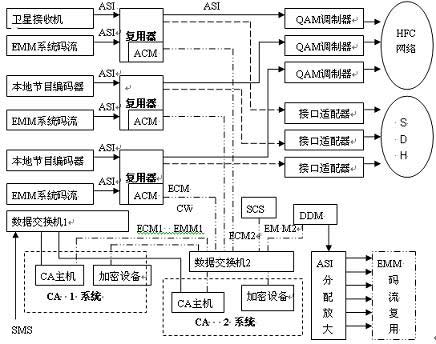
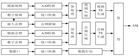
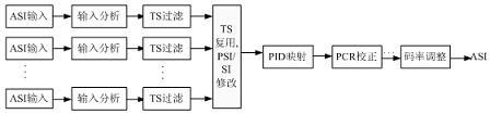
The cable digital TV system is composed of five links: source coding, multiplexing, channel coding and modulation, transmission channel, and digital set-top box. The analog video and audio signals are sampled, quantized and compressed according to the MPEG-2 standard to form the basic code stream ES. The basic code stream is divided into segments, and the corresponding header file is added to form a packaged basic code stream PES, and then the PES packets are segmented into TS streams with a fixed length of 188 bytes. The TS stream is multiplexed by the system to add PSI / SI information, encrypted information, etc. to form a multi-channel program transmission stream. Finally, 64QAM modulation and up-conversion are used to form a radio frequency signal for transmission in the HFC network, and the analog audio and video signal is decoded in the set-top box. This article focuses on the MPEG-2 coding standard and talks about the application of source coding and multiplexing technology in cable digital TV systems. The source coding and multiplexing transmission of standard definition digital TV SDTV in China's digital television system are based on the MPEG-2 international coding standard, and its coding rate can reach 3Mb / s ~ 50Mb / s, using the MP @ ML main class and main Level, the main aspect (MainLevel) image aspect ratio is 4: 3, the input image grid is 720 & TImes; 576 & TImes; 25, and the compressed bit rate is 4-8Mbps. Cable digital TV front-end signal source process The front-end signal sources of cable digital TV are mainly CCTV, satellite TV programs of various provinces and municipalities, digital TV pay programs and local TV programs of CCTV and provincial TV stations. Programs transmitted through satellite and national optical cable trunk lines are processed into digitally encoded and multiplexed SPTS and MPTS programs in their respective broadcast systems, and demultiplexed into ASI format TS streams by digital satellite receivers in the cable digital TV front-end computer room Send to the front-end multiplexer. Local TV station programs are transmitted to the cable front end through the metropolitan optical cable trunk, and then encoded in the front-end computer room and sent to the multiplexer for multiplexing and transmission with other programs. The following is a typical CATV signal flow chart. CATV front-end signal flow chart Coding process of local TV program Regardless of whether the hard disk has been broadcast, or the traditional baseband analog output of the local TV station's video and audio signals after A / D conversion or digital interface conversion, preprocessing, compression, 188-byte packaging and multiplexing, the final output SPTS stream. Among them, video and audio signal encoding and multiplexing adopt MPEG-2 standard. The video interface has CVBS, S terminal, SDI (embedded digital audio or non-embedded), etc., the video compression method is 4: 2: 0 or 4: 2: 2, the maximum bit rate can be 4: 2: 0 It reaches 15Mbps, and the maximum bit rate can reach 50Mbps at 4: 2: 2. Generally set at 4-8Mbps. Audio interfaces include RCA, XLR and AES / EBU, etc., and the code rate can reach 384Kbps. In addition to video and audio data, the encoder also includes PSI / SI and other information to be packaged and multiplexed together. The following is the flow chart of digital encoder signal processing: Digital encoder signal processing flow chart 3.1 Digital encoder requirements for analog video and audio indicators Due to the difference in the old and new equipment and the technology used in the local broadcasting system, the program quality is also uneven, and the encoding effect of the encoder is also different. During the A / D conversion process of the analog video and audio signals, the encoder cuts the signals that exceed the adjustable input amplitude range. For this reason, the analog video and audio input amplitude should be strictly within the standard range, otherwise, because the amplitude is overloaded, This causes distortion of the color of the picture, whitening, and excessive sound, which brings a serious response to the user's audio-visual feeling. The result of the measurement on the audio-visual measuring instrument is that the overloaded part of the audio-visual signal is cut, and a serious wave forms a square wave. 3.2 Compression processing of video and audio signals The video and audio signals of the local TV station are compressed and packaged into a SPTS stream, which is then multiplexed into the MPTS stream according to the plan and then re-multiplexed into the corresponding front-end multiplexer. The anti-interference ability of the digital encoder is very important. The out-of-band signal of the video is digitized to enter the in-band signal to cause interference. The digital encoding process is to separate the luminance and chrominance signals of the composite analog video signal, and then separately sample, quantize, and encode the luminance and chrominance signals. Because the video signal bandwidth of the PAL system is 0-5.75MHz, the spectral characteristics of the video brightness filter selected for this purpose are to allow lossless passage of the signal at 0-6.75Mhz, and the out-of-band rejection is 40dB at the 8MHz spectrum. In the application, it was found that when the digital coding equipment and the broadcast short-wave transmitter were together, although the short-wave frequency was around 8MHz-15MHz, due to the strong short-wave signal transmission power, it exceeded the encoder's out-of-band suppression capability. For this reason, in addition to useful video signals, the input video signals also carry short-wave signals with pulses approaching or exceeding the video amplitude. According to the principle of Zyquist sampling, the brightness sampling rate is 13.5MHz, and the sampling spectrum can cover from 6.75MHz to 20MHz. After the sampling process of the encoder, the unwanted signals outside the band are folded back into the video passband, which causes interference in the encoder. Therefore, for such interference, the grounding of the equipment room must reach the standard, the anti-interference performance of the video processing equipment should be good, the performance of the encoder input filter should be better, or an encoder with a higher sampling rate should be selected according to the specificity of the region. At the same time, in the compression process of the encoder, different video bitrates, audio bitrates and total system output bitrates should be configured according to the program type, and the higher the code rate for sports programs with more frequent active pictures, the higher the bitrate for still pictures. For multiple movies and news programs, the principle of lower bit rate is assigned. Since the encoder and multiplexer selected by the front end are not from a single manufacturer, statistical multiplexing between the two devices cannot be achieved. For this reason, the encoder output code rate is set to a fixed code rate. At the same time, since the total output bit rate of the system includes the sum of other overheads such as video bit rate, audio bit rate, and PCR bit rate, the total output bit rate of the system must be greater than the video bit rate. It is also found in practical applications that when the video bit rate of the input signal is set in the multiplexer, although the allocated video bit rate is higher than the video bit rate in the encoder, the signal appears because the total output bit rate of the system in the encoder is too high The mosaic phenomenon after passing through the multiplexer. It is analyzed as a secondary error of TR101290 in the code stream analyzer: PCR (PCR is used to recover the local 27MHz system clock decoded by the receiving end). The accuracy interval exceeds 40ms, which causes the jitter or drift of the receiving end clock and affects the screen display time. For this reason, the bit rate configuration must find a suitable point. If the bit rate configuration is too low, the picture clarity will be significantly reduced, and small block effects will occur. Signal multiplexing 4.1 The function of the multiplexer and the multiplexing process of the program After the satellite receiver demultiplexes, the ASI format CCTV and the provincial programs all carry their own PSI / SI tables. At the same time, these MPTS streams contain multiple sets of programs. The digital TV front-end will select the desired program according to its own overall program plan. Insert local PSI / SI tables and private data at the same time. For this reason, the selection multiplexer must have PID filtering, PID mapping, PCR correction, PSI / SI extraction, insertion, modification and other functions, and support the insertion and editing of private descriptors. And in order to deal with the high bit rate of the input signal, there must be a large buffer, including video, audio and system buffer, so as to avoid signal overflow and overflow. Among them, the SPTS stream code rate is about 4-8Mbps, which is limited by the highest effective code rate of the 64QAM modulator. The MPTS stream effective code rate is generally below 38.01Mbps. The following is the flow chart of multiplexer signal processing: Multiplexer signal processing flowchart In the process of program multiplexing, try to flexibly match the high bit rate SPTS and low bit rate SPTS signals, and control the highest effective bit rate below 38.01Mbps; MPTS programs are based on statistical multiplexing technology due to the previous coding multiplexing The bit rate is variable according to the content of the program. In order to save channel resources, the MPTS stream is not split, only the reading of the program tables, the re-mapping of the PAT and PMT tables, and the insertion of local CA and EPG data. The traditional multiplexer is based on time division multiplexing, the code rate of the encoder output is fixed, and there is a unidirectional relationship between the encoder and the multiplexer, while the more advanced multiplexer has statistical multiplexing function, encoding The two-way communication between the multiplexer and the multiplexer, the multiplexer reasonably allocates the effective rate of 38Mbps to different programs according to the amount of program data, and the output code rate of the encoder is variable. The traditional multiplexer is based on time division multiplexing, the code rate of the encoder output is fixed, the relationship between the encoder and the multiplexer is unidirectional, and the more advanced multiplexer has statistical multiplexing function. The encoder and the multiplexer are in two-way communication. The output bit rate of the encoder is variable. According to the amount of program data, the multiplexer reasonably allocates the effective rate of 38Mbps to different programs. The more advanced multiplexer also has a code rate correction function. By decoding the excessively high code stream to the program compression process, the quantization coefficient is adjusted to the code rate so that no abnormal signals such as mosaic appear in the 64QAM system. 4.2 Interface of encoder and multiplexer According to the digital TV front-end networking and diversification of signal sources, there are systems based on ASI signals, systems based on MPEGOVERIP and MPEGOVERSDH. For this reason, the output of the encoder and the input and output interfaces of the multiplexer include ASI / SPI, IP, DS3, etc. Users can flexibly configure various interfaces according to their own needs. 4.3 Network management system of encoding and multiplexer In addition to making some basic settings on the device panel, the encoder can also use the network management system to adjust and modify related parameters, and can also be operated remotely. Because there are many parameters that need to be adjusted in the digital TV multiplexer, including the modification of the program input / output table, adding ECM, EMM and other private data, for this reason, the stability, reliability and flexibility of its network management system are crucial important. If the operating system or network management software of the network management device is abnormal, EMM data and ECM data will be lost. In severe cases, users cannot receive CA data normally, which causes legitimate users to watch programs normally. Conclusion Encoders and multiplexers are the key source processing parts in digital TV systems. Whether their functions are comprehensive, the performance indicators are good or not, and the stability, reliability, and scalability of equipment and related software greatly affect the system broadcast Quality and operation of digital TV. For this reason, it is necessary to conduct a comprehensive inspection and test when selecting such equipment, so as to be more suitable for the operation of the system.
In the electrotechnics, the terminal refers to the terminal and is designed to run through the terminal production. The type is divided into single hole, double hole, socket, hook, etc. from the material, copper silver plating, copper zinc plating, copper, aluminum, iron, etc. their functions are mainly to transmit electrical signals or conduct electricity. The unit of terminal block is "bit", and one wiring bit is "bit". Usually the so-called table is the serial number of the terminal, which has different definitions in different applications. "Jie" and "bit" have the same meaning, but they are called differently. Groups are made up of sections.
Feed Through Terminal Block Section Feed Through Terminal Block ShenZhen Antenk Electronics Co,Ltd , https://www.antenk.com