For high-frequency circuits, the network method is required for analysis. At this time, the S parameter needs to be used. You can use the S parameters of the component manufacturers or you can build your own test circuit to measure the S parameters using a network analyzer. To understand S parameters in depth, you need to have sufficient basic knowledge of high-frequency electronic circuits. In the design of high-frequency circuits such as radio frequency and microwave, the node circuit theory is no longer applicable. It is necessary to use the analysis method of the step-by-step parameter circuit. This is a complex field analysis method, but more often the microwave network is used. Analyze the circuit. For microwave networks, the most important parameter is the S parameter. After the personal computer platform enters the GHz stage, from the computer's central processor, display interface, memory bus to I / O interface, all enter the high frequency The country of transmission, so now not only the S-parameters need to be understood and mastered in the design of radio frequency communication circuits, but designers of computer systems and even consumer electronics systems also need to have a grasp of relevant knowledge. The microwave system mainly studies the two major problems of signal and energy: the signal problem is mainly to study the amplitude frequency and phase frequency characteristics; the energy problem is mainly to study how the energy is efficiently transmitted. The microwave system mainly studies the two major problems of signal and energy: the signal problem is mainly to study the amplitude frequency and phase frequency characteristics; the energy problem is mainly to study how the energy is efficiently transmitted. The microwave system is a distributed parameter circuit, and the field analysis method must be used, but the field analysis method is too complicated, so a simplified analysis method is needed. In general, for a network, Y, Z and S parameters can be used for measurement and analysis, Y is the admittance parameter, Z is the impedance parameter, and S is the scattering parameter; the first two parameters are mainly used in the lumped circuit, Z and The Y parameter is very effective for the analysis of concentrated parameter circuits, and each parameter can be easily tested; but in microwave systems, due to the difficulty of determining the voltage and current of non-TEM waves, and there are practical difficulties in measuring voltage and current at microwave frequencies. Therefore, when dealing with high-frequency networks, the equivalent voltage and current as well as related impedance and admittance parameters become more abstract. The more consistent representation of the concepts of direct measurement of incident, reflected, and transmitted waves is the scattering parameter, the S-parameter matrix, which is more suitable for distributed parameter circuits. The S parameter is a network parameter based on the relationship between the incident wave and the reflected wave. It is suitable for microwave circuit analysis, and the circuit network is described by the reflected signal of the device port and the signal transmitted from the port to another port. Like the impedance and admittance matrix of the N-port network, the scattering matrix can also be used to describe the N-port network. The impedance and admittance matrix reflect the relationship between the total voltage and current at the port, while the scattering matrix reflects the relationship between the incident voltage wave and the reflected voltage wave at the port. The scattering parameters can be directly measured by a network analyzer, and can be calculated by network analysis technology. As long as the scattering parameters of the network are known, it can be transformed into other matrix parameters. For example, S11 is defined as the square root of the ratio of the energy reflected from Port1 to the input energy, and it is often simplified to the ratio of the equivalent reflected voltage and the equivalent incident voltage. The physical meaning of each parameter and the characteristics of the special network are as follows: S11: When port 2 matches, the reflection coefficient of port 1; S22: When port 1 matches, the reflection coefficient of port 2; S12: When port 1 matches, the reverse transmission coefficient from port 2 to port 1; S21: when port 2 matches, the forward transmission coefficient of port 1 to port 2; For reciprocal networks, there are: S12 = S21; For symmetric networks, there are: S11 = S22 For lossless networks, there are: (S11) 2 + (S12) 2 = 1; S21 indicates the insertion loss, that is, how much energy is transmitted to the destination (Port2). The larger the value, the better. The ideal value is 1, which is 0dB. The larger the S21, the higher the transmission efficiency. It is generally recommended that S21> 0.7, that is ï¼3dB. The single transmission line we often use, or a via, can be equivalent to a two-port network, with one end connected to the input signal and the other end to the output signal. If Port1 is used as the signal input port, Port2 is used as the signal output port , Then S11 represents the return loss, that is, how much energy is reflected back to the source (Port1), the smaller the value, the better, it is generally recommended that S11 "0.1, that is -20dB, S21 represents the insertion loss, that is, how much energy It is transmitted to the destination (Port2). The larger the value, the better. The ideal value is 1, which is 0dB. The larger the S21 is, the higher the transmission efficiency is. It is generally recommended that S21> 0.7, which is -3dB. If the network is lossless, as long as the reflection on Port1 is small, it can meet the requirements of S21》 0.7, but the usual transmission line is lossy, especially above GHz, the loss is very significant, even if there is no reflection on Port1, After a long distance transmission line, the value of S21 will become very small, indicating that the energy has been consumed on the road before reaching the destination during the transmission process. In low-frequency circuits, the size of the components can be ignored relative to the wavelength of the signal (usually less than one tenth of the wavelength). In this case, the circuit is called a node (Lump) circuit. The voltage and current laws are used to calculate the circuit. The basic characteristics of the circuit during the loop are:
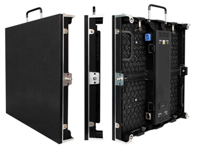
China Indoor Rental Led Display is Ultra thin body, die-casting aluminium structure, high-accuracy CNC cutting panel. Natural aluminium heat conduction design, no fans ,no noise. Good consistency, no particle and mosaic phenomenon.
LCD window monitoring function. Use LCD monitoring screen to detect exact temperature, voltage, working time,etc.
Front and rear service both available .Support quick maintenance within 5 seconds with magnetic tools.
Low power consumption,fast heat sinking, long life span time,fast lock system.
Large viewing angle reach to 140° both horizontal and vertical sides.
Using die-casting aluminium material ,extremely light weight and thin thickness
For pair locks of the cabinets, with adjusting function to achieve the seamless splicing. Side spring dowel and up location pin of the cabinets to make sure the flatness of the led screen.
Billion level color and high brightness high with quality LED,realizing perfect of gray scale and contrast.
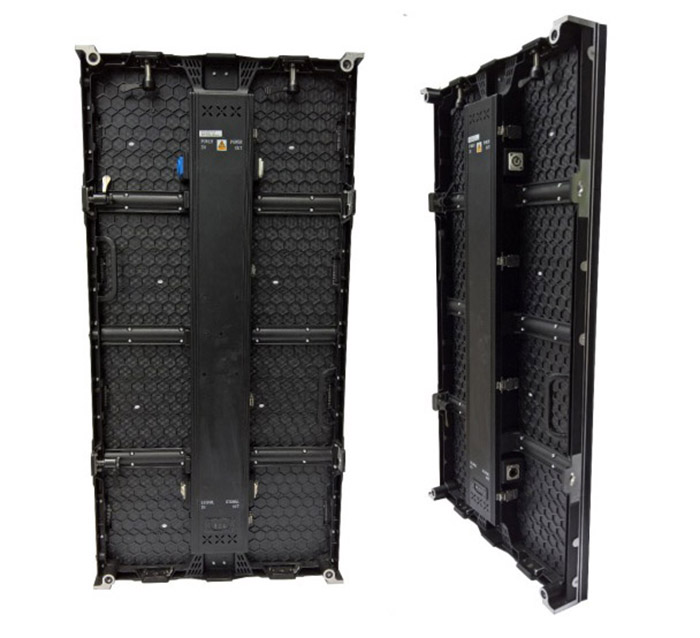
Stable and continue high-quality video for high-end applications. Low power consumption and environmentally friendly. 500x500mm and 500x1000mm panel sizes. Guarantee of consistency in years. Straight and curved cabinets can be connected together seamlessly by lock.
RCFG file can be saved to factory. If you loose the RCFG file, just click" restore factory".
At the bottom of cabinet, there is special design which can help to protect lamp during installation. 110-220V power input and DVI,HDMI,SDI,DP signal input.
Available pixel pitch from P2.5mm, P3mm, P3.2mm P3.9 and P4.8mm, with SMD 2121 black LED lamps, MBI high refresh control IC, Novastar and Linsn control system. Packed in road/flight case for easy transportation. Can both hang from truss and stack on the ground. Curved locks allow concave and convex surface. Easy to install and dismantle. Ideal design and products for rental/stage business.
Indoor Rental Led Display,Indoor Rental Led Screen,Indoor High Resolution Led Display,Rental Led Display For Indoor Shenzhen Bako Vision Technology Co., Ltd. , http://www.rentalleddisplays.com
The field analysis method must be used for distributed parameter circuits, but the field analysis method is too complicated, so a simplified analysis method is needed. The microwave network method is widely used in the analysis of microwave systems. It is an equivalent circuit method. On the basis of the analysis of the field distribution, the microwave element is equivalent to a reactance or resistance device by the way, and the actual guided wave transmission system is used. Effective as a transmission line, thereby simplifying the actual microwave system into a microwave network, and solving the problem of the field into the problem of the road. Microwave network theory is developed on the basis of low-frequency network theory. Low-frequency circuit analysis is a special case of microwave circuit analysis. 
as the picture shows. The two-port network has four S-parameters. Sij stands for energy injected from port j and measured energy at port i. 

