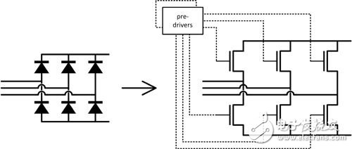
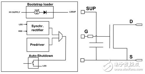
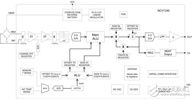
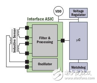
Today's cars are moving toward providing energy efficiency while minimizing environmental impact. But in the long run, non-oil-based power systems seem to be the most promising solutions; at the same time, the automotive industry is introducing more improvements based on existing technology. A major trend is hybridizaTIon, where micro-hybrids (including stop-start systems) and mild hybrids have significant growth opportunities. These “moderate hybrid†solutions may seem overdone, but the industry is still doing a lot of electronic and mechanical development around these applications. This article will first look at some excellent examples of continuous improvement related to Lundell-type motors (the more widely known name is "alternator"). Thanks to better electronic control, its energy efficiency is improved, more energy is recovered, and the effects of frequent engine start-up are handled smoothly. The second part of this article will focus on more sensors added to the car, which will help further reduce the dependence of traditional internal combustion engines on oil. The last paragraph explains how existing inductive sensor technology can optimize the brake pedal to help the car save more energy. Start alternator In starting an alternator system, the passive rectifier diode is replaced by a high current switch. These switches are responsible for driving the alternator to act as a motor (starter mode) and performing synchronous rectification (alternator mode) on the stator current generated inside the alternator. Synchronous rectification greatly increases the energy efficiency of the alternator by diverting the (substance) diodes with highly conductive channels, reducing the forward voltage drop to less than 150 mV. Figure 1: Synchronous rectification in an alternator One of the main functional challenges of this application is to ensure that the switch is turned off very quickly when the stator current is reversed; any delay in switching off will result in unnecessary battery discharge in much the same way as a conventional diode reverse recovery. In view of this, the pre-driver IC includes a high-curvature driver operating inside the autonomous gate control loop and is designed to achieve the best possible trade-off between ohmic losses and transition losses when the current sign changes during rectification. Integrating these pre-drivers in an IC is quite complicated. First, it requires multiple different voltage domains to coexist on the same silicon substrate while ensuring reliable communication between these voltage domains. Second, the driver IC that starts the alternator is placed in the worst-case location, potentially subject to battery reversal, load dump, cathode ground transfer, and extremely large dV/dt in the stator phase (on the order of microseconds) 100 V), electromagnetic interference and many other transient events. Similarly, using differential techniques and careful management of parasitic (bipolar) effects on silicon substrates, it is possible to build such ICs using cost-effective buck technology rather than silicon-on-insulator (SOI) technology. Figure 2: Starting a MOSFET with a strong pre-driver to control the high gate-source capacitance (Cgs) in the alternator In addition to traditional lead-acid batteries, we see more and more energy storage components being used in power-supply networks in start-stop systems, such as lithium-ion batteries, supercapacitors, and so on. In these systems, the security realm becomes as important as the core functionality. Therefore, we see that ISO26262 safety standards are increasingly entering our field of vision, sometimes resulting in a considerable portion of the silicon area dedicated to monitoring applications, testing the operational health of this IC and its companion IC, and where needed Underneath to ensure a safe state. Finally, the combination of smart circuits and high-power components in close proximity indicates that the junction temperature of the control circuit has risen sharply; it is not uncommon to consider that the operating junction temperature is above 175 °C in the application. In addition, during the component certification phase, temperatures up to 200 ° C may be used to further accelerate the aging process to maintain a useful life test period within a reasonable 2,000 hours. This challenge can be effectively addressed by using a silicon process with an extended temperature range and taking design constraints into account during the design phase. Sensing technology used in internal combustion engines Sensors are bringing unprecedented levels of energy efficiency to contemporary internal combustion engines while minimizing emissions. For example, a flow of air (MAF) sensor measures the amount of air entering the engine's combustion chamber to accurately inject the proper amount of fuel. At the other end of the engine, an oxygen and nitrogen oxide (NOx) sensor directly measures the exhaust gas composition and feeds the information back to the engine control unit (ECU). The advancement of pressure sensors is virtually ubiquitous, representing a trend that is accompanied by the evolution of internal combustion engines and the pursuit of enhanced control. Originally a Manifold Absolute Pressure (MAP) sensor, this sensor is an alternative to using a MAF sensor. With advances in fuel injection technology, direct injection (GDI) and direct diesel (DDI) pressure sensors are required to match the fuel pressure injected by a common rail fuel line that is directly connected to each cylinder combustion chamber. The latter sometimes requires a diesel particulate filter (DPF) to reduce soot, while the DPF requires sensors to help maintain proper operating conditions. Even outside the engine, the tire pressure monitoring system (TPMS) ensures that the tires are properly inflated, providing not only better safety, but also higher fuel efficiency as the rolling resistance of the tire is reduced. Another frontal position of the pressure sensor is the combustion chamber itself. In order to provide the final combustion control, one of the necessary conditions is to accurately know the pressure in all cylinders at all times. Certain types of clean diesel engines have been operated with the help of in-cylinder pressure sensors. Those same sensors are also key drivers of the new engine being studied. One example is homogeneous charge compression ignition (HCCI), which is designed to combine the low emissions of gasoline engines with the energy efficiency of diesel engines. All of these advances present new technical challenges that require increasingly complex integrated electronic circuits to meet these challenges. For example, better control requires higher accuracy, and the current 0.5% tolerance is common. At the same time, as the layout of the pressure sensing function moves closer to the center of the engine, the operating temperature range continues to expand. This imposes additional restrictions on the sensing elements and the electronic circuitry required to compensate for their non-ideal characteristics. A block diagram of a new generation of pressure sensor ICs is shown in Figure 3. The low-noise analog front end begins to provide high-precision performance, followed by a high-precision sigma-delta analog-to-digital converter (ADC). Complex digital signal processing provides nonlinear temperature compensation for the offset and sensitivity of the sensing element. Common 5 V analog outputs are gradually replaced by standard digital outputs such as single-sided nibble transmission (SENT) and PSI5. This method reduces the totalization error by eliminating the output digital-to-analog conversion in the sensor and the analog-to-digital conversion at the ECU. Each sensor is calibrated at the time of production and the compensation factor is stored in the internal EEPROM. Figure 3: Block diagram of the next generation of precision signal conditioning interface ICs for pressure sensors Inductive position sensor interface for brake pedals A typical brake pedal has only one switch that helps determine when the brake light should be turned on. As the brake energy recovery (regen) function is added, a new brake pedal position sensor is required. Essentially, the standard friction brake system is upgraded with a control system that measures the precise displacement of the brake pedal. The friction brake system does not activate when the brake pedal is only slightly displaced. In this "recovery belt", the energy recovery system will measure the brake pedal displacement and determine how much of the moving energy of the moving car needs to be transferred to the temporary energy storage. This energy storage can take many forms; original equipment manufacturers (OEMs) may prefer pneumatic or hydraulic accumulators, 48 ​​V batteries, supercapacitors, or even flywheels. A mild hybrid will convert the stored energy back to a limited amount of propulsion in the next acceleration phase, while the micro-hybrid uses only electrical recycling technology to power the boardnet for a longer period of time. To measure the exact position of the brake pedal during the "recovery belt", a similar technique as used for the accelerator pedal can be used. Figure 4 shows a block diagram of a contactless sensor solution for this type of application. Figure 4: Inductive Position Sensor Application Block Diagram The custom inductive sensor interface developed by ON Semiconductor leverages advanced front-end filters and incorporates intelligent processing. The on-chip driver stimulates the sensor with at least one excitation inductance. The coupled output inductor of the sensor produces a signal that contains information about the relative position of the magnetizing inductance and the output inductor. The change in relative position of the inductor depends to a large extent on the sensor design chosen, which is usually the result of linear or rotational motion. This integrated circuit then converts the electrical input and output signals of the sensor into digital position information. The resolved position signal is then transmitted to the microcontroller via the interface, depending on the customer's requirements or preferences. A proprietary mixed-signal scheme can be chosen to match the sensor interface output format, including proportional voltage, sine-cosine (Sin-Cos) voltage, pulse width modulation (PWM), SENT or PSI5. In addition to the required skills, semiconductor suppliers in the sensor field should also be in a correct attitude to the ISO26262 standard. Many pedal applications in automobiles are directly related to safety and need to be addressed through the appropriate ISO26262 understanding, methods, and toolset. Inductive sensors can be used in redundant configurations that share the same results with certain functions and provide independent data output, meeting ASIL-D requirements at the module level. Emerging recycling applications, combined with new suitable safety standards, are driving the industry toward the development of new integrated circuits that connect to inductive sensors. Electronic component developers and suppliers are moving towards the future of car power systems creating differences on the road. While micro-hybrid and mild hybrid vehicles offer relatively modest fuel economy improvements, they are cost effective. It is precisely this gradual improvement of the car that will gradually evolve most cars towards new technologies, while also building the foundation of the next generation of power systems. Buffet Warmer,Food Warmer,Stainless Steel Food Warmer,Unter Top Buffet Food Warmer Shaoxing Haoda Electrical Appliance Co.,Ltd , https://www.hotplates.nl