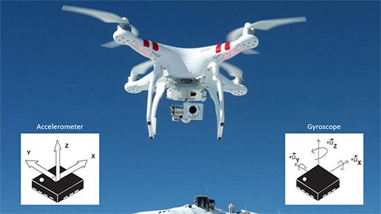
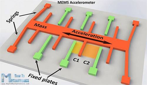
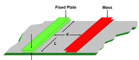
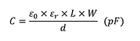
Accelerometers and gyroscopes are sensors used to acquire acceleration and rotation information from drones, cell phones, automobiles, airplanes, and mobile IoT devices. However, accelerometers and gyroscopes are prone to errors, accelerometers may be noisy, and gyroscopes may drift, requiring designers to adopt novel methods to achieve the highest accuracy. One method is to apply sensor fusion. This article will evaluate accelerometers and gyroscopes separately to see how these noise and drift errors are generated. An example of these two sensors will be presented next, and how sensor fusion techniques can be used to combine the results of these two sensors and reduce the effects of these errors. Choose the right sensor Accelerometers are used to measure all linear forces applied to an object in millivolts per gram (mV/g). Moving objects exhibit dynamic motion, such as acceleration, and continue to be subject to the static force of gravity. When the accelerometer is attached to an object, the acceleration of the object and the gravitational force acting on the object can be measured. However, accelerometers are prone to positional errors over time. Figure 1: A drone with a 3D accelerometer and a 3D gyro sensor can successfully provide position feedback to the ground controls. (Source: Wikipedia and STMicroelectronics) The gyroscope provides the rate of change of the angular velocity of the object over time, in mV/deg/sec (mV/deg/sec). When the gyroscope is connected to the object, the sensor can smoothly measure the angular change of the object, but like the accelerometer, the gyroscope will have a stable and increased angular error over time. Many accelerometers and gyroscopes are manufactured using microelectromechanical systems (MEMS). In the production of MEMS sensors, silicon components and mechanical components are combined on the same micron-sized silicon substrate. The main components in these devices are mechanical components, sensing mechanisms, and application specific integrated circuits (ASICs). MEMS accelerometer The structure of individual MEMS accelerometers uses a fixed silicon plate and a mechanical spring for responding to external forces (Figure 2). Figure 2: The MEMS accelerometer model uses silicon and mechanical components to derive capacitance changes based on changes in acceleration. (Source: HowToMechatronics.com) The general MEMS sensing technology uses on-chip variable capacitors. During motion, the green fixed plate remains stationary while the orange weight bends along the acceleration axis. With this movement, the capacitance values ​​C1 and C2 vary with the distance between the fixed plate and the weight. Figure 3: Close-up of a MEMS accelerometer capacitor structure. (Source: Digi-Key Electronics) In terms of quantity, the change in C1 and C2 values ​​depends on the distance d between the capacitor plates (Figure 3). to sum up When designers try to extract more accurate information from moving objects, using 3D MEMS accelerometers and gyroscopes, coupled with sensor fusion strategies, provides a reliable solution for motion and navigation problems. Ningbo Autrends International Trade Co.,Ltd. , https://www.vapee-cigarettes.com