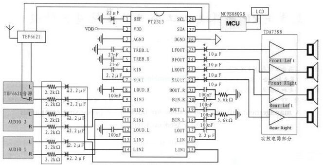
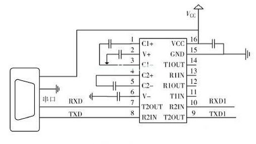
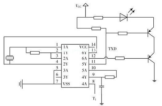
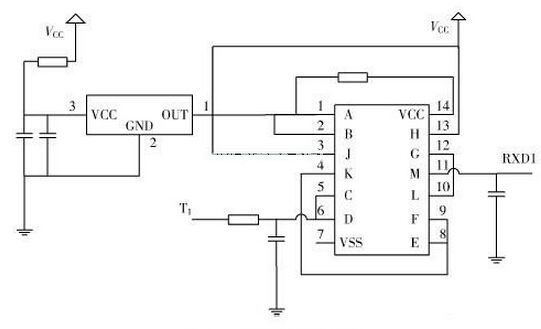
As the car changes from a transit tool to a personalized consumer product that combines leisure and entertainment, consumers' demands for car entertainment continue to increase, and the automotive industry is facing strong market pressure, which needs to be reduced without sacrificing performance. Cost, this phenomenon is particularly evident in the entry-level automotive market, and consumer demand for low-cost vehicles has allowed the low-end media entertainment market to grow at an annual rate of more than 10%. AM/FM radios are especially popular for their low cost and high sound quality. How to design a broadcast audio product that meets both cost control requirements and high-quality audio enjoyment to meet the demand for cost reduction and simple design in this field has become the focus of the industry. We can imagine the continuous improvement and continuous innovation of the radio, making the development of the radio more and more. This article refers to the address: http:// How to design a broadcast audio product that meets both cost control requirements and high-quality audio enjoyment to meet the demand for cost reduction and simple design in this field has become the focus of the industry. In order to realize low-cost AM/FM car radio application, this paper introduces low-cost microcontroller MC9S08QG8, integrated radio chip TEF6621, low-cost audio processing and high-fidelity power output scheme, and reduces the hardware design circuit, while describing the device selection and overall Build ideas and hardware design details. This design can meet the requirements of low power consumption, low cost, high performance and high sound quality. The specific design of the hardware circuit According to the previous device selection and overall construction considerations, the specific design circuit of the AM/FM car radio completed in this paper is shown in Fig. 4. Most of the pins of the MC9S08QG8 microcontroller (MCU) have multiple functions. In the circuit design, the MC9S08QG8 is used as the control core to realize various control such as display, tuning, audio sound, and power amplifier output. AM/FM car radio hardware block diagram The schematic diagram of the AM/FM car radio application here is divided into three parts. The first part is the basic connection required for the MC9S08QG8 MCU. The second part is the TEF6621 tuner and antenna receiving circuit, the third part is the audio processing and power amplifying output circuit composed of PT2313 and TDA7388, and the fourth part is the human-computer interaction circuit of 16x2 LCD and code potentiometer. The standard voltage of the car battery is 12/24 V. In this design, the DC-DC voltage adjustment circuit is used to output 1 channel 9 V voltage and 1 channel 5 V voltage. The microcontroller, display part and other low voltage peripheral parts are powered by 5 V. The digital voltage, the tuner TEF6621 and the audio chip PT2313 are powered by 9 V, and the power amplifier TDA7388 is powered by the car battery. The clock circuit of the MCU does not need an external crystal oscillator, and directly uses the clock that is built in the MCU. The TEF6621 tuner, PT2313, TDA7388 and its peripheral circuits use the minimum hardware requirements for the work provided in the data sheet. The connection between the MCU and the TEF6621 tuner and PT2313 is connected according to the standard IIC mode. The MCU is the master, and the TEF6621 and PT2313 are the slaves. The SDA and SCL signal lines are basically configured and operated on the two devices through different slave addresses to realize tuning. With tuning function. MCU's 8K FLASH and 512 bytes of memory resources are sufficient for basic radio control. In addition, if further expansion of functions is required on the basis of this system, the on-chip resources are tight, and Freescale also provides pin-to-pin compatibility. Low-cost upgrade solution such as MC908QG16/32. Analysis of the principle of RS232 serial port to infrared communication circuit As a means of data transmission, infrared communication can be applied in many occasions, such as infrared remote control of home appliances, entertainment facilities, automatic meter reading of water, electricity and gas energy consumption measurement. Especially in the electronic power industry, there are more and more products using infrared technology for communication. People can use infrared technology to make short-distance copy control of products, which is very simple and convenient. The serial port is a very common device communication protocol on a computer. Most computers include an RS 232-based serial port. The concept of serial communication is very simple. The serial port sends and receives bytes in bits. The communication described in this article is done using 3 lines: ground; send; receive. Since serial communication is asynchronous, a port can send data on one line while receiving data on another line. Level conversion Since the level of the RS 232 signal is inconsistent with the level of the serial port signal of the microcontroller, level conversion between the two must be performed. The MAX232 is commonly used to implement RS232/TTL level conversion. The MAX232 internal structure has three parts: (1) Charge pump circuit. It consists of 1~6 pins and 4 capacitors. (2) Data conversion channel. Two data channels are composed of 7~14 pins. RS 232 data is converted from R1in, R2in input to TTL/COMS data and output from R1out, R2out; TTL/COMS data is converted from T1in, T2in input to RS 232 data from T1out, T2out to computer DB9 port. (3) External power supply circuit. External power supply is the use of computer USB output +5 V power supply effective power supply, not only saves the design of the circuit, and saves volume in actual production, the circuit principle is shown in Figure 1. Figure 1 circuit schematic Infrared emitting part When the infrared transmitting end transmits data, the binary data to be transmitted is modulated into a series of burst signals and transmitted, and the infrared carrier is a square wave with a frequency of 38 kHz. The infrared carrier can be realized by the PWM function of the internal timer of the microcontroller, or it can be realized by the peripheral hardware circuit. Here, the 38 kHz crystal oscillator is used to generate a stable oscillation signal, and the CD4069 non-gate circuit is used to realize the square wave oscillation signal through a series of conversions. The level-converted COMS data signals are superimposed to drive the triode conduction, thereby realizing the TSAL6200 infrared emission diode to convert the periodic electrical signal into a certain frequency of infrared light signal, as shown in Figure 2. Figure 2 shows the infrared emission end Infrared receiving part The infrared receiver adopts the HS0038B infrared receiver. The principle of the infrared receiving circuit is: when receiving the carrier signal of 38 kHz, the HS0038B receiver will output a low level, otherwise it will output a high level, so that the infrared light signal can be demodulated into a certain period. The continuous square wave signal can be recovered by the single chip microcomputer to recover the original data signal. HS0038B is a miniaturized receiving device capable of receiving infrared signals. Its epoxy package can be used as an infrared filter, so there is no need to add an infrared filter. The biggest advantage is that the output is also very stable in highly disturbing environments. The circuit design is shown in Figure 3. In this paper, the CD4093 logic NAND gate chip and HS0038B receiver are used to build the circuit output data. At the same time, the other level of the chip pins are used to self-lock the conversion level data of the MAX232 output to avoid the signal self-receiving. . Figure 3 circuit design diagram I-Beam Inductors,Chip Inductors,Color Ring Inductor,R-Bar Inductors Shenzhen Sichuangge Magneto-electric Co. , Ltd , https://www.scginductor.com