This article refers to the address: http:// A challenging AM/FM radio performance test is an assessment of adjacent and/or alternate channel performance because the radio must receive a weaker signal when a strong adjacent RF signal is present. To evaluate the subjective reception quality between different radios, OEM car radio manufacturers often implement test plans based on specific site routes in different regions. For example, when driving in a city, you usually encounter an RF environment called the “City Canyonâ€, in which large buildings produce complex multipath and shadow patterns for FM stations. People often use channel emulators to reproduce typical multipath models for a particular channel. However, this approach is not practical when multiple emulators are needed to simulate adjacent channel interference. One reason is that the automotive industry still uses field test driving methods to optimize the radio. Figure 5: Frequency response of the notch filter measured by the microwave vector network analyzer. Both generators are set to FM mode: Generator 1 has frequencies of 107.1, 107.3, 107.5, and 107.7 MHz, output power is +3 dBm, provides 1 kHz modulated tone, stereo mode, and 75 kHz offset; generator 2 frequency is 106.7 MHz The output power is -62dBm, providing 1kHz modulation tone, mono mode and 22.5kHz offset.
Aluminium wire as a good anticorrosion material,in steel structure surface anti-corrosion(container,dam and sluice gate,Ductile Iron Pipe,bridge etc.)
Aluminum Wire,Zinc Aluminum Wire,High Pure Aluminum Wire,Aluminum Alloy Welding Wire Shaoxing Tianlong Tin Materials Co.,Ltd. , http://www.tianlongspray.com
Commercial vehicle AM/FM radios must be able to work reliably in a variety of environments. Because designers of these radios use digital signal processing (DSP) algorithms to overcome effects such as reflections, signal multipath and fading, they often spend several weeks on-site analyzing the effects of different signal conditions. A more practical and less time-consuming solution is to simulate the various conditions encountered in the field using the real-recorded radio signal to simulate the car's AM/FM radio design.
However, test driving methods can only show major repeatability issues. Due to changes in the weather and the proximity of large vehicles, the state of signal transmission will constantly change, so no test results will be obtained for either test. In addition, since test driving is done over a large area, it is critical to accurately assess the AM/FM radio design performance in different regions. Fortunately, due to the continuous development of RF signal recording and storage technology, recording real FM broadcast signals can completely replace the traditional test driving method to achieve commercial AM/FM radio design evaluation.
For example, Averna's RF recording and playback system captures the full FM band (20MHz bandwidth) with 14-bit resolution. The digital recorder uses National Instruments' NI PXI hardware architecture to simultaneously record GPS position, radio audio, and record video of the driving test using an onboard camera. The system has an 80dB spurious-free dynamic range (SFDR) and looks quite large, but the FM receiver can handle a wider range of signal levels from -2dBuV to +110dBuV (-109 to +3dBm).
In Detroit, USA, a "difficult to reproduce" extreme dynamic range test case was used to evaluate the ability of the radio to mitigate strong adjacent interference effects. During this test drive, the local 3kW transmitter was operating at 107.1MHz to interfere with the 106.7MHz signal from Detroit. During test travel, the interference source power varies between 5dBV and 95dBV, while the target channel power varies between 25dBV and 50dBV. In addition to multipath fading, there is also a shadow effect from tall buildings that occasionally blocks direct line of sight reception. This fading is difficult to model with the model in the RF signal generator, and is more suitable for recording and playback signal simulation.
Figure 1 shows the test drive on the map this time, with a 3kW launch rack on the roof of a tall building. Although the antenna is in the direct line of sight, the source of the interference is at the peak level, and the received signal quality of the 106.7 MHz target frequency is seriously degraded. Figure 2 shows a typical spectrum of signal strength, and Figure 3 shows the intensity of two signals during the test run. 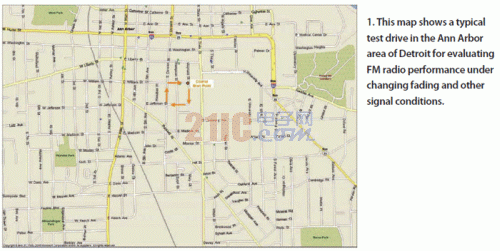
Figure 1: The map of the route for this test.
Although the dynamic range indicator for the RF recording and playback system is 80 dB, the actual recording shows an available dynamic range of approximately 60 dB to 65 dB. This reduction in dynamic range can be explained by the saturation of the digitizer and the peak-to-average ratio (PAR) of the multi-carrier signal. To avoid possible saturation of the digitizer (signal clipping), the recorded data must be at least 5 dB below the saturation level. For multi-carrier signals such as FM bands or COFDM signals in urban environments, the recorded signal typically has a PAR of 10 dB to 15 dB because of the vector superposition of multiple RF signals in the 20 MHz passband of the RF signal chain. The combination of these two factors enables a usable dynamic range of 60dB to 65dB enabling high quality multi-carrier recording. 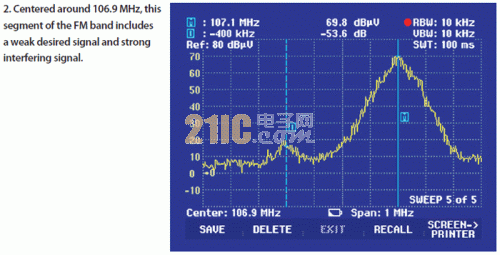
Figure 2: Typical spectrum of signal strength.
Despite these limitations, if a strong interferer (greater than 40 dB) does not appear in the band of interest, the RF recording and playback system is proven to effectively capture both multipath and weak signals. This system uses a low noise amplifier with a noise figure better than 2 dB to capture weak signals in rural areas, with no significant degradation in signal quality, and considers impedance mismatch. This RF recording and playback system is designed for 50Ω impedance, while conventional automotive FM antennas and/or radio inputs are matched to 75Ω at FM and high impedance (above 1.5kΩ) at AM. 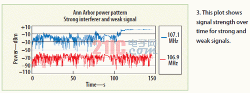
Figure 3: The strength of the two signals during the test drive.
Figure 4 is a block diagram of the recommended solution. The program uses a Universal Receiver Tester (URT) to replicate test conditions like the radio environment described above. Weak signals are received in the presence of strong sources of interference and obstacles such as multipath effects. The first generator (generator 1) provides a powerful source of interference. Since the noise floor of this interference source is very high at the weak signal frequency point, it is necessary to suppress this by using a notch filter before combining it with the weak signal generated by the second generator (generator 2) to simulate the target signal. noise. The notch filter uses a three-pole cavity filter that can be tuned in the 10MHz range with at least 50dB of rejection (Figure 5). 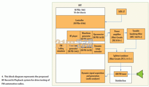
Figure 4: Recommended solution for the RF Recording & Playback System for driving test car FM radios.
Generator 2 is used with a Dynamic Range Extender (DRX), which is a programmable attenuator. The noise floor is simultaneously attenuated by providing attenuation of the target signal. In addition, the multipath fading effect can be imposed on the weak signal because the DRX response time is sufficient to react to the fading curve (nominal value is 40 times per second). For testing purposes, the radio is mounted in a shielded enclosure to suppress potential interference from external signals. 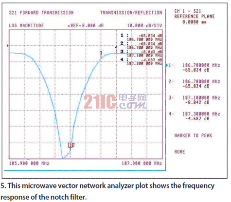
Under the above hardware configuration and performance conditions, the RF signal state must be accurately presented from the generator output. A powerful source of interference is provided by the generator 1 from the field radio frequency recording of the FM band. The Universal Receiver Tester (URT) RF recorder is used to capture signals during test driving in typical climatic conditions. The weak signal is generated by the generator 2, and an FM fading simulator, a .wav file format track, and a power curve playback obtained when the weak signal is recorded in the field are required.
Multipath fading is a common signal impairment that occurs when a mobile signal is received. For FM signals, multipath fading can result in signal loss up to several times per second, depending on the speed of the vehicle. Compared to a more comprehensive standard channel emulator with various effects, the FM fading simulator can provide a flat drop attenuation response to the test signal, and this multipath approximation is usually sufficient to test the FM tuner performance.
The FM fading simulator allows the use of test tones like the standard AM/FM generator, or the specified .wav file format audio track to be modulated. In addition, the envelope of the generated signal can be modulated by playback of a tab-delimited text file. The power mode envelope can be extracted by simple signal processing of any pre-recorded FM signal by using a simple tool in the playback tool suite.
Figure 6 depicts the basic functions of the test set. The ability to play back any specified audio signal or track and apply multipath flattening impairments to the target signal provides additional freedom that is not possible in field testing. This is important because the DSP algorithm being designed will react differently depending on the type of audio program. 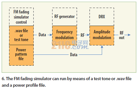
Figure 6: The FM fading simulator can be implemented with test tones or .wav files and power mode files.
For the convenience of case analysis, it is assumed that the power of the target weak signal is 30 dBμV, the power of the strong interference source is 110 dBμV, and the frequency is 400 kHz away from the target signal. This will be the most rigorous test applied to FM radios and is the typical scenario encountered in the worst part of the test drive (Figure 7). After these experimental conditions are set, the effective dynamic range of the system can be calculated. The dynamic range of this test system at the frequency of interest is about 115 dB with a live ADC recording dynamic range of approximately 65 dB and an FM cavity notch filter with approximately 50 dB rejection. 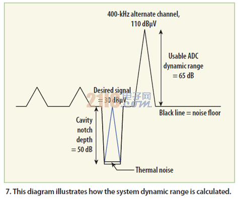
Figure 7: Calculation of the dynamic range of the system.
It is necessary to make an accurate judgment of whether 115dB is sufficient for testing the standard FM radio. How much dynamic range the test requires depends on several conditions: the FM receiver has a noise figure of 4 dB, the wideband AGC threshold is about 80 dBV, the noise figure is increased by 1 dB due to the interference signal strength exceeding the wideband AGC threshold, and the RF interference signal is only 110 dBV. According to the last three assumptions, the receiver sensitivity will be reduced by 80dB to 110dB or 30dB. Therefore, the noise floor of the FM radio receiver in this case is -15dBV + 4dB (because of the noise figure) + 30dB (because of the de-sensitivity) or 19dBV. The RF dynamic range required for the test is 91dB (110dB-19dB), allowing the device to provide more than 20dB of margin for case measurements.
The measuring device is tested prior to use of the system to confirm that the measuring device does not cause any significant noise or distortion that may degrade the measurement accuracy. The power level is also calibrated by adjusting the relative insertion values. The specified level is measured at the synthesizer output, the radio antenna connection point. Linearity is measured above the required signal level. To do this, the two generators must be set to CW mode at their respective frequencies, and the total power level must exceed the value used in the test case. Referring to Figure 8, generator 1 is set to 0 dBm and generator 2 is set to -20 dBm. There is no measurable third-order intermodulation (IM3). Figure 7 depicts the signal that is set to approximate the maximum test condition. 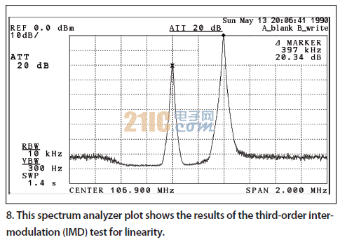
The spectrum analyzer waveforms shown in Figures 8 and 9 demonstrate that the power level is accurate and there is no IM3 introduced due to the integration of the two signal generators. Additional tests have shown that the notch filter does effectively suppress noise from the generator, and subsequent measurements at the frequency of interest are limited to thermal noise rather than noise from the test system. Audio measurements are made at the output of the test receiver using a URT audio analyzer at different offsets in the center frequency of the interfering signal. Thus, the receiver desensitization effect will prove that the noise floor of the device does not affect the measurement of the test case. 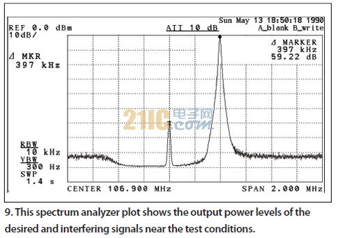
The following phenomenon is observed at different generator 1 frequency set points: if the test device has a limiting factor, the signal-to-noise ratio (SNR) of the audio does not change as the interfering RF signal is far away. As shown in the table, the desensitization of the receiver is caused by a strong source of interference, proving that the noise from the test set is not a limiting factor for the 106.7 MHz test frequency point.
The signal used to excite the test receiver is taken from the broadcast RF signal, which is captured during the test drive. Audio listening tests are done by professional listeners.
The audio track comes from the output of the same test receiver used during live recording and the Averna lab. There is also a radio frequency signal that is played back by the generator 1 of the device among the recorded signals. Finally, generator 2 is used with the URTFM fading simulator to generate a weak signal of 106.7 MHz. The .wav file used by the FM fading simulator has the same content and trajectory as the air audio recording made during the test drive.
The test work is summarized as follows: The URT RF player is turned on. The FM fading simulator provides the target RF signal for testing and transmits it to the test receiver. The test receiver is tuned to a weak signal of 106.7 MHz. The audio from the test receiver is then recorded during RF playback, and then the recorded audio collected from the field is listened to by trained professional listeners. Then the recorded audio collected from the test set is listened to in the lab. The two audio recordings are then compared in terms of fidelity and quality to determine if signal degradation has occurred due to environmental or signal fading effects. After comparing the audio records, the records were found to be similar. Both audio recordings contain the same noise reduction effects from the receiver's built-in DSP, such as stereo to mono switching and audio high frequency cutoff. In addition, further listening tests were performed for weak signal applications and without multipath fading, so that the receiver desensitization effect was isolated.
This method is a valuable engineering test tool that can be used to isolate in-situ damage changes for a deeper understanding and optimization of audio quality. In addition, this method can be applied to a wide range of other radios.