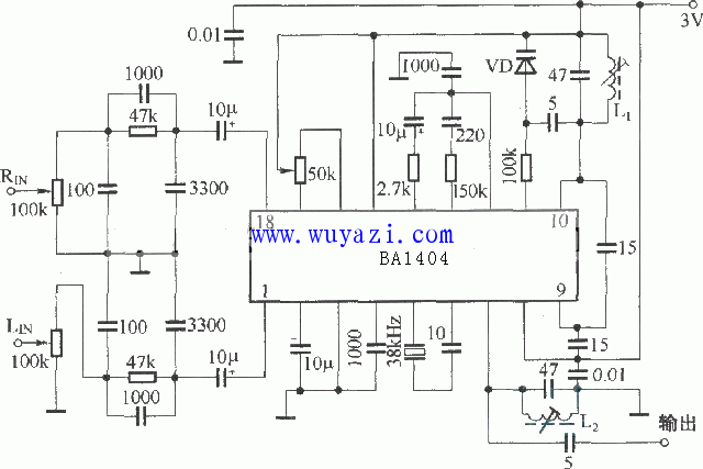
Today, I’d like to share with FM enthusiasts a BA1404-based FM stereo transmission circuit. The BA1404 is a dedicated FM IC known for its excellent performance and stability. It's widely used not only in FM broadcasting but also in radio remote control applications. The IC operates on a low voltage range of 1.5V to 3V, making it ideal for small and compact circuits. Its design is efficient, requiring minimal external components, which makes it easy to implement and reliable in operation. However, to get the best performance from the BA1404, there are several important considerations you should keep in mind: First, to ensure compatibility with standard FM broadcast receivers, a pre-emphasis circuit with a time constant of 50 μs should be connected in series with the left and right channel inputs. This helps match the frequency response of the transmitter to that of the receiver. If you're using this IC in a remote control application, you can combine the left and right inputs and connect them to the signal source through a 0.1 to 1 μF capacitor. Second, the external R and C components connected to pins 12 to 14 play a crucial role in combining the stereo modulator output and the pilot signal into a composite signal. These components help maintain consistent phase characteristics between the two signals, ensuring good channel separation. These values are typically fixed, and any changes should be made after thorough testing to avoid performance issues. Third, when using stereo modulation, the maximum audio frequency should not exceed 19 kHz. If your input signal contains pulsed noise or interference, it’s recommended to add a low-pass filter at the input stage. This helps prevent distortion, buzzing, and degradation of channel separation. Fourth, pins 16 and 17 are used for balance adjustment. Even if these pins are not connected, the circuit can still deliver acceptable sound quality. However, in normal operation, it's common to use a 50kΩ potentiometer to fine-tune the DC balance, which further enhances the overall resolution and clarity of the transmitted signal. Finally, the DC output voltage at pin 11 is internally set to 0.7V above VDD, so no external adjustment is needed for this pin. Below is a simple 1K meter stereo FM transmitter circuit diagram using the BA1404 IC, which demonstrates how the components are arranged for basic operation. 2.54mm Pitch 2.54mm Pitch HuiZhou Antenk Electronics Co., LTD , https://www.atkconn.com