Application of parallel and redundant technology of rail type switching power supply in practice
This paper analyzes the double parallel boost three-phase based on single-cycle control technology. Â PFC Â The rectifier input current tracking error is poor when the grid voltage is asymmetrical, and an effective improvement measure is proposed. By calculating the phase voltage asymmetry coefficient, the duty cycle calculation formula is corrected to eliminate the asymmetric voltage to the input current. The effect of poor waveform tracking is such that each phase current is in phase with its own voltage, achieving unity power factor and low current distortion. At any time, the rectifier only needs two switching tubes to operate in a high frequency state, thereby further reducing the overall loss of the switching tubes. Finally, the correctness of the control strategy is verified by hardware experiments.
1 Introduction
In the past ten years, with the development of power electronics technology, many large-capacity motor speed control systems, household appliances and other equipment need to supply various AC/DC to the AC grid. Â Or AC/DC / AC conversion. The power conversion using a conventional diode or thyristor for the nonlinear converter of the power switch tube will generate various current harmonics in the power grid, seriously interfere with the normal operation of other electrical equipment, increase power consumption, and at the same time The grid power factor is greatly reduced, reducing the effective transmission capacity of the grid. To this end, the International Electrotechnical Commission's IEC1000-3-3 and IEC519 have stricted the current harmonics and electromagnetic interference quality of the rectifier equipment. In order to meet these requirements, national scholars on Power Factor Correction, Â PFC Â The technology has been studied in depth and has achieved a series of results. Now, PFC Â Technology has become one of the important research directions in the field of power electronics. At present, single-phase PFC technology has become more and more mature in circuit topology and control strategy. However, since three-phase PFC rectifiers are coupled to each other, a relatively complicated control algorithm is required, and its output power is large, and the power grid is polluted. More serious, so the research and implementation of three-phase power factor correction technology has become an important research focus in recent years.
The control of three-phase PFC rectifiers mainly includes two types: semi-decoupling and full decoupling. The mainstream control algorithms include space vector modulation based on dq decoupling, hysteresis comparison algorithm and single-cycle control. Space vector modulation requires a dq decoupling control algorithm for the input voltage, which requires a digital signal processor DSP. The hysteresis comparison algorithm has a constant switching frequency, and the input and output interference is relatively large, requiring relatively large inductors and capacitors as filter elements.
The three-phase PFC rectifier based on single-cycle control has been studied intensively. The controller is a novel controller that does not require a multiplier. It only needs simple integration and addition and subtraction of the input current, and directly with the reference voltage. The switching element control waveform of the constant modulation frequency can be realized by comparison. The controller has both dual functions of modulation and control. The average value of the input current controlled during the control period can be just proportional to the control reference signal in steady state or transient conditions. It has fast dynamic response and stable switching frequency. , robust, easy to implement and so on. Thus it becomes the mainstream control algorithm for three-phase PFC rectifiers. However, when the three-phase input voltage is symmetrical, the input current can maintain a low current distortion while the three-phase voltage is asymmetrical, but the input current will phase shift with the input voltage and fail to reach unit power. The control target of the factor. Based on the analysis of the cause of phase shift of the controller, an improved control strategy is proposed to make the input current of each phase still in phase with the input voltage under the condition of three-phase input voltage asymmetry. Factor and low current harmonics.
2 system structure and equation of state
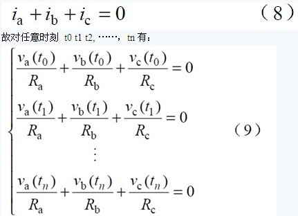
Figure 1 shows the main circuit schematic of a dual shunt boost three-phase rectifier. In addition, Figure 2 also shows the waveform of the three-phase voltage when the input voltage b phase amplitude is reduced by 20% and the phase c phase is delayed by 30 °, and is divided into six intervals according to the broken line. It should be noted that the input voltage is asymmetrical, and the partition points may be different. The partition point is determined by the instantaneous maximum amplitude difference point of each phase non-zero sequence voltage. According to the principle of six-stage PWM control technology, the three-phase rectifier can achieve unit power factor by controlling the on and off of two switches in each interval of the linear period.
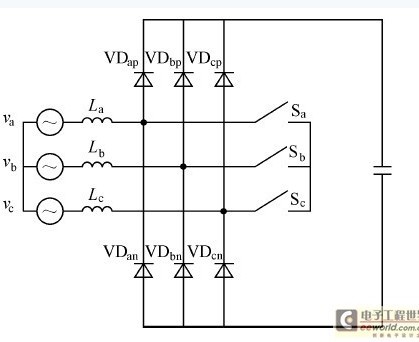
Fig.1 Main circuit topology diagram of double parallel boost type three-phase rectifier
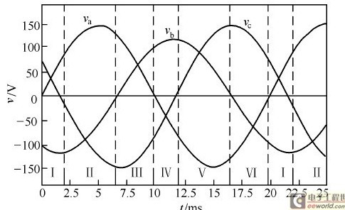
Fig. 2 Waveform of the three-phase voltage when the b-phase amplitude is reduced by 20% and the c-phase is delayed by 30 °
Before starting the detailed analysis, assume that the input voltage is a sine wave, the three-phase circuit parameters are symmetrical, and the forward impedance and other parasitic parameters of the power components are ignored. Taking the voltage shown in Figure 2 as the main circuit input in Figure 1, for example, in the interval I, the switch Sb is always in the on state, and only the switches Sa and Sc are controlled. At this time, the three-phase rectifier can be decoupled as shown in the figure. 3 Dual parallel boost topology shown.
In the figure, Vp and Vn are the voltages corresponding to different intervals, Lp, Ln and Lt are the inductances corresponding to different intervals, Tp and Tn are the main control switches corresponding to different intervals, and dp and dn are the duty ratios of the main control switches. . Since the PWM switching frequency is much higher than the grid frequency, the average value of the voltage of each inductor is zero in one switching cycle. The loop current method and the node voltage method are used to divide the various switching states.

with
Thus launched

among them
It can be proved that the two kinds of switching sequences of Equation 1 are established in any interval, and as long as the circuit works in the continuous conduction mode, the equation can accurately reflect the input voltage, output voltage and duty ratio of the steady-state circuit. The fixed relationship between them is independent of the control scheme used. Therefore, Equation 1 is the equation of state for the rectifier.
3 Effect of asymmetric voltage on input current
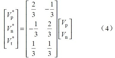
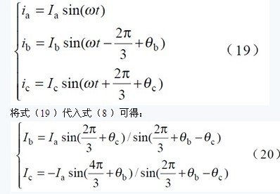
Construct a three-phase PFC rectifier according to Equation 4, and make va = Reia , vb = Reib and vc = Reic according to the three-phase voltage symmetry and the goal of achieving unit power factor, and then according to va+vb+vc=0 and ia+ib+ The constraint of ic=0 knows that as long as the two-phase current is controlled to track the voltage of the corresponding phase, the other phase current can also be tracked. From this, the formula for calculating the duty ratio of the unit power factor is calculated:
When the input voltage is asymmetrical, va+vb+vc=0 is not necessarily true. If the duty cycle function of single-cycle control is still used according to Equation 5, the phase currents are:
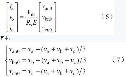
That is, van0, vbn0, and vcn0 are the portions of each phase voltage that do not contain the zero sequence voltage. It can be seen from equations (6) and (7) that the current of each phase can still maintain low current distortion. However, if (va+vb+vc)/3≠0, there will be a phase difference between the input current and the input voltage, resulting in the system not achieving the unit power factor. In order for the system to still achieve the goal of unity power factor, the system's control strategy must be improved.
4 Improved control strategy
4.1 Calculation of phase voltage asymmetry coefficient
When the three-phase input voltage is asymmetrical, it is assumed that each phase current tracks the respective phase voltages, so that the equivalent resistances of the respective neutral lines from the input end are Ra, Rb and Rc. Because the system uses three-phase three-wire system at any time:
Since the grid voltage may have various disturbances, in order to make the calculation result as accurate as possible, n sampling voltages in one or several cycles can be divided into multiple groups, and two of them are used to calculate the phase voltage asymmetry coefficient. Adding the two groups to equation (9) gives:
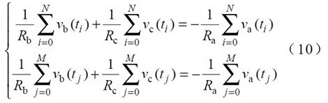
From this

Equation (11) is a formula for calculating the phase voltage asymmetry coefficient, where λa , λb and λc are the phase voltage asymmetry coefficients and Re is the standard equivalent resistance. It can be seen that when the grid voltage is asymmetrical, the equivalent resistance values ​​of the phases are different in order to enable the phase currents to correctly track the corresponding phase voltages. In particular, if the three-phase voltage is symmetrical, λa = λb = λc =1, then Ra = Rb = Rc = Re.
4.2 Â PFC Â Control Strategy
Since the three-phase input voltage is asymmetrical, in order to achieve a unit power factor, each phase current can track the respective phase voltages, namely:
According to the equation (3), the interval I can be used as an example, and the inductor currents iLb iLc can be controlled by the control switches Tp and Tn corresponding to changes in V*p and V*n. Since there are in the I interval:

Substituting equation (8) and (12) into equation (13):
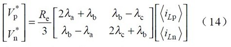
Substituting equation (14) into equation (3) yields:
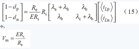
Where - Rs equivalent current monitoring resistor. Vm -- The output voltage of the feedback voltage loop compensator.
At this time, the formula (15) can be expressed as
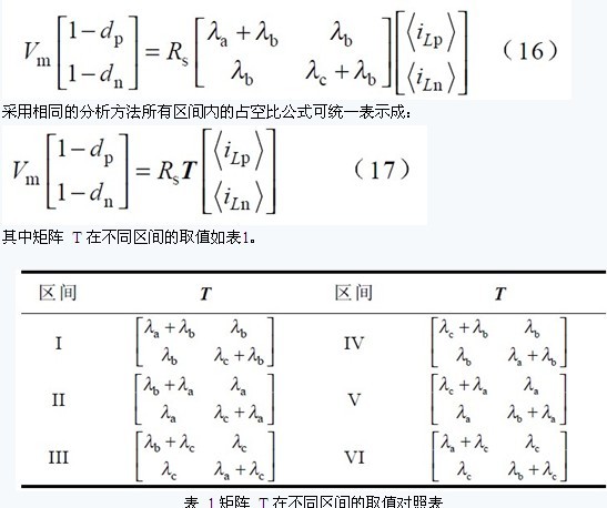
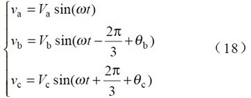
It can be known from equation (17) that if the switches Tp and Tn are controlled such that the switching duty ratios dp and dn satisfy the linear combination of the equations, a three-phase PFC can be realized. Therefore, equation (17) is improved to achieve unity power factor. Key function. When the input voltage is symmetrical, λa = λb = λc = 1, and equation (17) is simplified to equation (5).
4.3 Proportion of current amplitude distribution of each phase under improved strategy conditions
The following is a detailed analysis of the proportion of the current amplitude distribution of each phase when the rectifier is controlled according to the improved strategy. Without loss of generality, assume that the three-phase input voltage is:
Since the control strategy of the improved strategy is to track the corresponding phase voltages for each phase input current, the input current of each phase can be expressed as:
From the formula (20), the following three conclusions can be drawn:
1 The distribution ratio of the current amplitude of each phase is only related to the offset angle of the input phase voltage, and is independent of the magnitude of the input voltage of each phase. And within a certain range, the larger the offset angle, the larger the current amplitude distribution ratio of the phase.
2 If the input phase voltage is phase-symmetric, that is, θb = θc = 0, the input phase current is symmetrical.
3 When the input phase is missing, since the current of the missing phase must be 0, it can be known from equations (8) and (20) that the currents of the other two phases must also be zero. At this time, the rectifier cannot work normally.
5 Experimental research
In order to verify the correctness of the above theoretical analysis, a 2kW three-phase PFC is built according to the main circuit topology shown in Figure 1.  experiment system. The experimental system uses TI's TMS 320LF2407 as the core control module of the whole system, which realizes the control functions of interval judgment, phase voltage asymmetry coefficient calculation, duty cycle calculation and PWM modulation. The main parameters of the system are: input inductance La=Lb=Lc=10mH, output capacitance C0=470μF, main switching component adopts MTY25N60E, rectifier diode adopts MUR3080; system output is DC 400V; switching frequency is 5kHz; load resistance is; output The power is 1.6kW; the experimental input current and phase a voltage are shown in Figure 4. The oscilloscope voltage waveform is 50V/div and the current waveform is 5A/div; the time t of Figure 4a and Figure 4b is 4ms/div; The time t is 100ms/div. Comparing the current waveform of Figure 4, you can find:
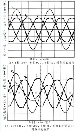
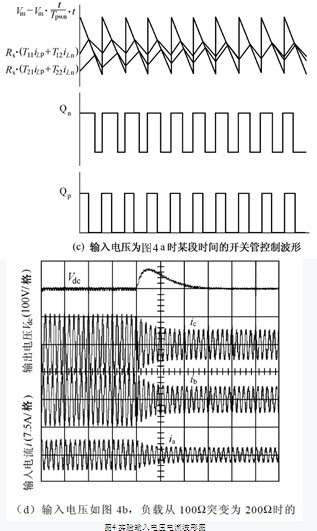
1 As long as the three-phase voltage is phase-symmetric, the input current is symmetrical.
2 When the phase is asymmetrical, the current amplitude difference of each phase is relatively large.
The 3-unit power factor control method will phase shift the input current when the input voltage is asymmetrical, and the unit power factor cannot be realized.
4 From Fig. 4d, it can be seen that the dynamic response time of the system is about 4 power supply cycles, which is roughly equivalent to the dynamic response time of the system using the literature [1] algorithm. The Fourier analysis of each current waveform in Fig. 4a and Fig. 4b shows that the THD of each phase is below 3% and the power factor is about 99.98%, which further verifies the correctness of the improved control strategy under the condition of input symmetry or asymmetry. Each phase current can track the phase voltage well and achieve a unit power factor.
6 Conclusion
In this paper, the problem of input current tracking input voltage is poor under the condition of input voltage asymmetry in dual-parallel step-up three-phase PFC rectifier based on single-cycle control technology, and an improved control algorithm is given. The algorithm calculates the phase voltage asymmetry coefficient of the input grid voltage through the sampling voltage of one or several cycles, and corrects the calculation formula of the unit power factor, so that the input current of each phase can still track the phase voltage well. Unit power factor and low current distortion. Compared with other types of three-phase PFC rectifiers, the controller has the advantages of reliable operation, simple control scheme, simple operation, and unity power factor and low current even in the case of input voltage asymmetry. distortion. With the rapid development of DSP technology and technology, the cost of high-performance DSP hardware is getting lower and lower. The implementation of this controller with high-performance DSP will greatly reduce the circuit complexity and have a good application prospect.
Features: 12v Dc geared motor drive precision, small volume, large torque, low noise, durability, low energy consumption, customized power design,easy installation, easy maintenance;Simplify design and save space.
12V Dc Gear Motor, namely gear reduction motor, is based on ordinary Dc Motor, coupled with gear reduction gearbox.
The gear reducer is used to provide low speed and large torque.
At the same time, the gearbox with different deceleration ratio can provide different speed and torque.
Generally different industries, using different power dc motor, generally adopt custom parameter design pattern.


Method of use: the best stable in horizontal plane, installed on the 12v dc gear motor output shaft parts, cannot use a hammer to knock,knock prone to press into the 12v dc gear motor drive, may cause damage to internal components, and cannot be used in the case of blocked.

Operating temperature range:
12v Dc geared motors should be used at a temperature of -10~60℃.
The figures stated in the catalog specifications are based on use at ordinary room temperature catalog specifications re based on use at ordinary room temperature (approximately20~25℃.
If a geared motor is used outside the prescribed temperature range,the grease on the gearhead area will become unable to function normally and the motor will become unable to start.Depending on the temperature conditions ,it may be possible to deal with them by changing the grease of the motor's parts.Please feel free to consult with us about this.
Storage temperature range:
12v Dc geared motors should be stored ta a temperature of -15~65℃.
In case of storage outside this range,the grease on the gearhead area will become unable to function normally and the motor will become unable to start.
Service life:
The longevity of 12v Dc geared motor is greatly affected by the load conditions , the mode of operation,the environment of use ,etc.Therefore,it is necessary to check the conditions under which the product will actually be used .The following conditions will have a negative effect on longevity.Please consult with us should any of them apply.â—Use with a load that exceeds the rated torque
â—Frequent starting
â—Momentary reversals of turning direction
â—Impact loads
â—Long-term continuous operation
â—Forced turning using the output shaft
â—Use in which the permitted overhang load or the permitted thrust load is exceeded
â—A pulse drive ,e.g.,a short break,counter electromotive force,PWM control
â—Use of a voltage that is nonstandard as regards the rated voltage
â—Use outside the prescribed temperature or relative-humidity range,or in a special environment.
â—Please consult with us about these or any other conditions of use that may apply,so that we can be sure that you select the most appropriate model.


when it come to volume production,we're a major player as well .each month,we rurn out 600000 units,all of which are compliant with the rohs directive.Have any questions or special needed, please contact us, we have the engineer group and best sales department to service to you Looking forward to your inquiry. Welcome to our factory.

12V Dc Gear Motor,Dc Gear Motor 12V,12V Gear Motor,12V Dc Gear Motor 30 RPM
Shenzhen Shunchang Motor Co., LTD. , https://www.scgearmotor.com