In recent years, with the popularization of automobiles and the construction of roads, inter-city economic exchanges have become more frequent, and the area of ​​activities has become larger and larger, resulting in serious problems such as traffic congestion, increased car accidents, and increased emissions. The emergence of the Intelligent Transport System has effectively improved the above various traffic problems. The vehicle monitoring system is a branch of the intelligent transportation system. It combines advanced wireless positioning technology, geographic information system and modern mobile communication technology. It not only plays a major role in the intelligent transportation system, but also provides anti-theft and anti-robbery alarms and emergency. Medical help, entertainment and other services. All of these have prompted various R&D institutions to vigorously develop vehicle monitoring systems. This paper selects the design and implementation of the vehicle terminal modules in the whole system. This article refers to the address: http:// 1 Overall structure of vehicle monitoring system The entire system consists of GPS satellites, vehicle terminals, communication networks (GPRS and Internet) and monitoring centers. During the running of the vehicle, the GPS receiver of the vehicle terminal receives the positioning data, calculates the current longitude, latitude, speed, heading and other information (time, status) of the vehicle, and then transmits it to the monitoring with static IP address through the GPRS network. Center, and the depositor center database. After receiving the information uploaded by the vehicle, the monitoring center scientifically schedules and manages according to the current situation of the vehicle, thereby improving operational efficiency. Customers can also check the current status of a particular vehicle via the Internet or by phone. The overall structure of the system is shown in Figure 1. 2 Car terminal function The satellite receiving module of the vehicle GPS/GPRS terminal collects GPS satellite data, and obtains the geographical coordinate information of the vehicle through data processing. After the information is processed by the vehicle terminal, it is sent by the GPRS wireless communication module to the GPRS wireless communication network. The GPRS network establishes a data channel supporting TCP/lP between the vehicle terminal and the monitoring center of the access network according to the corresponding protocol. The car GPS/GPRS terminal relies on the interaction of information between the data channel and the monitoring center. The monitoring center can also send control commands and service information down through this channel. In addition, in addition to vehicle positioning, the system can also provide various services such as anti-theft and anti-grab, power off and power off mobile vehicles, display scheduling information, medical help, mobile phones and the like. 3 car terminal hardware design The vehicle terminal hardware system is based on single-chip microcomputer and GPS+GPRS module, and belongs to economical function terminal. Its structure is shown in Figure 2. relay,electric relay,timer relay,general relay,finder relay Zhejiang Kaimin Electric Co., Ltd. , https://www.ckmineinverter.com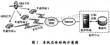


3.1 Information Processing and Control Module
The AVR series of single-chip microcomputer system, the main function is to carry out information processing and control the operation of each component of the vehicle station in accordance with the requirements of the communication protocol. The module consists of a CPU, external memory, I/O interface, and control logic. The CPU is implemented by ATMEGA64(L) microcontroller, which is based on the enhanced AVR RISO structure of low-power 8-bit CMOS microcontrollers, its advanced instruction set and single clock cycle instruction execution time, ATMEGA64(L) data. The throughput rate is up to 1 MIPS / MHz, which can slow down the system's contradiction between power consumption and processing speed. The microcontroller has two serial ports for communication with the GPS and GPRS modules.
3.2 GSM / GPRS + GPS module
SIMCOM's SIM508 module is used. The SIM508 module is a product that fully integrates tri-band GSM / GPRS and 20-channel capable GPS into one module (34 mm × 55 mm × 3 mm). The product is designed to meet the requirements of automotive applications (temperature, humidity, shock, etc.). In particular, the SIM508 with integrated components can save a lot of time and cost. The SIM508 supports NMEA-0183, SiRF binary and RTCM SC-104 three GPS data formats to meet different design requirements. The vehicle terminal obtains the specific location of the vehicle through the GPS part of the module. After being processed by the CPU, it is displayed to the user and sent to the monitoring center through the GPRS part to realize real-time positioning and tracking of the vehicle, and at the same time, realize voice and short Message communication function.
3.3 input and output modules
The output is realized by the 12232F liquid crystal module, and can display graphics or 7.5 × 2 (16 × 16 dot matrix) Chinese characters. The interface with the external CPU can be parallel or serial. Considering the simplicity of programming, the vehicle terminal uses strings. Line interface connection.
There are two ways to input the vehicle terminal: remote control input (main input device) and handle input. Taking into account the limitations of the handle input in an emergency, the remote control is used as the main input device, which can be used to complete functions such as voice dialing, sending and receiving short messages, medical help, maintenance and assistance, and opening and closing devices. The handle device includes four function keys: confirmation, return and up and down, which are designed for user input.
4 car terminal software design
The software system adopts a modular design method. Each module implements a function or a protocol. Each functional module appears as a sub-function, which shortens the software development time, is easy to modify and transplant, and at the same time, when writing software, it still has Some software application interfaces facilitate software upgrades, such as adding new protocols. The software system function module is shown in Figure 3.
4.1 System Workflow
The main function of the vehicle terminal software system is completed by the main program. The main program uses the system structure of the state machine, and its workflow
As shown in Figure 4
When the program works, the GPS and GPRS serial port initialization work is performed first, and then enters the main control loop. In the main control loop, first identify whether the GPS data is valid, that is, whether the positioning is successful. If the positioning is successful, the system goes to the next state to establish a GPRS connection, otherwise it is relocated. After the GPRS connection is established, the processed positioning data can be sent to the monitoring center. At the same time, during the running of the main program, the remote controller can also input an interrupt request in response to other functions.
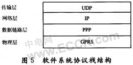
4.2 Software System Protocol Stack
Drawing on the OSI model and the standard TCP/IP protocol stack, the system uses a four-layer network transport protocol: transport layer, network layer, data link layer and physical layer. The structure of the system protocol stack is shown in Figure 5.
Taking into account the tens, hundreds or even thousands of vehicle-mounted terminals in the vehicle monitoring system, for such applications with multiple points of dispersion, small amount of data, high real-time requirements, and a large number of terminals, the transmission layer adopts UDP more than TCP. a little better. As a network layer protocol, the IP protocol mainly cuts the data stream into appropriate sizes, and then routes the data packets to the destination IP by using different routes. Above the physical layer, the PPP protocol acts as the only designated data link layer protocol for GPRS over the physical layer, transforming the original physical layer connection into an error-free data link by means of CRC check and acknowledgment. After the PPP negotiation succeeds, the system will successfully log in to the Internet remotely and get the IP assigned by the gateway to itself. The physical layer channel between the terminal and the network is the GPRS connection. The specific GPRS protocol has been implemented in the GPRS modem. After the data terminal is set to the correct AT command of the GPRS modem, the AT dialing command can be used for dial-up connection. When receiving the dial-up feedback response of the GPRS modem, a physical channel is received. That is, the GPRS channel is established between the terminal and the network.
5 Conclusion
This paper introduces an implementation scheme of GPS/GPRS-based vehicle monitoring system terminal, and gives detailed software and hardware components and design implementation. After many times, the system is stable and the effect is good. The system can be applied to the hand command monitoring system, the city rental car management department