The intelligent trend of modern instrumentation has made the application of various sensors increasingly widespread. Due to the many advantages of lasers, laser detection and control systems developed with these features have advanced technical performance, convenient performance and a compact system structure. The laser sensor is generally composed of a laser generator, an optical component, and an optoelectronic device. It can convert the measured physical quantity (such as distance, flow, speed, etc.) into an optical signal, and then apply the photoelectric converter to turn the optical signal into an electrical signal. The output signal is obtained by filtering, amplifying, and rectifying the corresponding circuit, thereby calculating the measured value. With the advantages of laser (such as good directionality, high brightness, good monochromaticity, good coherence, etc.), laser sensors usually have simple and reliable structure, strong anti-interference ability, non-mechanical contact, high resolution and high precision. It has the advantages of small indication error, good stability and suitable for rapid measurement. This article refers to the address: http:// With the continuous development of science and technology, the country's requirements for super-supervised work are constantly improving. Whether in terms of efficiency or precision, intelligent over-limit detection tools will be widely used. In view of the above situation, a high-efficiency and high-precision intelligent vehicle ultra-wide and ultra-high detection system based on laser scanning sensor technology is designed. 1 Measuring principle of laser ranging sensor Laser ranging is an active optical detection method. The detection mechanism of active optical detection is: the detection system transmits a beam to the target (in optical detection, generally infrared or visible light), and the beam is reflected by the target surface to generate an echo signal. The echo signal contains the information to be tested directly or indirectly. The receiving and signal processing system obtains the measured signal by receiving and analyzing the echo signal. The laser has the advantages of strong coherence, high brightness and good directionality. Therefore, after the laser appeared, it became the preferred light source for most active optical detection systems. At present, pulsed laser ranging has been widely used, such as topographic survey, earth-to-moon distance measurement. Figure 1 is a schematic diagram of a pulsed laser ranging system. The working principle is as follows: the man-machine operation sends a ranging command, triggering the laser to emit a laser pulse, and a small amount of energy is transmitted through the beam splitter as a reference pulse to the pulse acquisition system. As the starting point of the timing, the digital ranging timer is started to start timing; the other gang is reflected by the refractive prism and is directed toward the target. Generally, the front end of the transmitting end has a telescopic optical system, in order to reduce the divergence angle of the outgoing beam, to increase the light energy surface density, increase the working distance, and also reduce the interference between the background and surrounding non-targets. A part of the laser beam reaching the target is diffusely reflected back to the range finder; the receiving objective lens and the optical filter reach the detector APD. The main function of the narrow-band optical filter is to make full use of the excellent monochromaticity of the laser to improve the system. Signal-to-noise ratio; the photodetector APD converts the optical signal into an electrical signal, and then amplifies, filters, and shapes the electrical signal. The shaped echo signal turns off the time interval processing module, causing it to stop timing. In this way, according to the result t of the time interval processing, the distance L of the object to be tested can be calculated as: In the formula (1), c is the speed of light. In Figure 1, the filter and aperture reduce the effects of background and miscellaneous flash and reduce background noise in the detector's output signal. According to formula (1), the pulse ranging accuracy ΔL can be expressed as: △L=c△t/2 (2) 2 system composition and data processing The system uses the LMS series outdoor non-contact laser sensor of SICK Company of Germany as the data acquisition equipment, and the industrial control machine as the data processing equipment. The system composition is shown in Figure 2. The L MS series sensor is an outdoor non-contact high-precision, high-resolution external sensor. Its working principle is based on the measurement of the laser beam flight time. It emits laser pulses at defined intervals and is calculated by a timer. The time interval between the transmitted pulse and the received pulse is used to obtain the distance from the measured object. The pulsed laser beam is scanned by a reflection of a rotating mirror inside the ranging sensor to form a sector scan of the surrounding environment. The sequence of pulses of the target object is determined by a series of pulse sequences received. The scanning frequency of the LMS sensor is 25Hz/50Hz, the angular frequency is (0.25°/0.5°, the scanning angle range is 0°~270°, the maximum scanning distance is 20 m, and the standard measurement accuracy is ±0.30 m, safety protection level It is IP67, which is safe for human eyes. The harsh environmental factors have no influence on the measurement range, and can be used in the outdoor temperature range of -30 to +50 ° C. The LMS series laser sensor uses the laser pulse ranging method to calculate the scanning of the measured object. The distance from the point to the sensor on the contour line is uploaded to the industrial computer for post-processing through the high-speed network interface in real time in the form of polar coordinates. Since the data transmission speed of the network port can reach 100Mb/s, there will be no data loss problem. It ensures that the measured data can be uploaded to the industrial computer for data processing in real time. The industrial computer directly exchanges data with Winsock and LMS series sensors in the visual programming language VB. When using Winsock control, first consider Use TCP or UDP communication protocol. TCP communication protocol control is the communication protocol that requires connection, similar to the telephone system. According to the transmission, the user must first establish a connection, and there is an error checking mechanism to prevent the data from being distributed and transmitted. The transmission process is slow and the error is less. If the data is more important, it is better to use this method. The UDP communication protocol is a communication protocol that does not require a connection. The transmission between two computers is similar to the delivery of mail: information is transferred from one computer to another, but there is no clear connection between the two. Compared with the way, its error check is relatively simple, so the speed is faster, and when using speed, it is more appropriate to use this method. The system has high requirements for real-time data, and the accuracy of data is relatively low. Therefore, before data exchange, the IP addresses of LMS series sensors and IPCs must be set to one network segment respectively, and then UDP communication is used. Protocol to exchange data. After receiving the polar coordinate information uploaded by the LMS series sensor, the industrial computer processes all the data through the data processing program based on the VB core design. The data processing process is as follows. First, the data uploaded by the sensor is used to judge the entry and exit of the vehicle. In the second step, the polar coordinates of the measured point are converted into plane rectangular coordinates by the transformation of the coordinate system, that is, The third step is to compare y1, y2, y3, ..., yn, respectively, to take the smallest y value ymin; then compare x1, x2, x3, ..., xn respectively to take the leftmost x value of the scanned vehicle. Xmin and the rightmost x value xmax; calculate the maximum height of the vehicle for a single scan Height=H-ymin and maximum width Width=xmax-xmin (H is the height of the sensor from the ground). The width and height of the single measurement are compared with the height, and the incoming and outgoing vehicles are judged based on the change curve of the data. Then, by comparing the width and height information of each single-measured vehicle, the maximum height Height and the maximum width Width of the vehicle are calculated. Finally, the maximum width and maximum height of the passing vehicles are compared with the vehicle width and height limits specified by the state to determine whether the passing vehicles are super wide and super high. The comparison results are displayed on the display of the industrial computer and saved. Measure the results to the SQL database. If the vehicle is super wide and super high, the industrial computer will also generate an audible and visual alarm to remind the Supervisor and the driver of the over-limit vehicle that there is an overrun problem. 3 Experimental results and analysis The laser sensor in this system is installed on the gantry with a height of 6 m. The scanning area of ​​the laser sensor is perpendicular to the lane. When the vehicle passes through the scanning area of ​​the sector, the detection system automatically calculates the width and height of the vehicle. The value is displayed on the display of the industrial computer for monitoring by the staff. During the on-site experiment, the vehicle's width and height (hereinafter referred to as actual values ​​and measured values) were measured by manual and automatic methods for 30 different types of passing vehicles. The statistical analysis results show that there are 28 vehicles with an error of 0.10 m in the automatic measurement data of the system. There are 2 cars within 0.15 m. That is, 93% of the vehicle detection error is less than 0.10 m, which satisfies the requirement that the user's error is less than 0.15 m. The data analysis table is shown in Table 1. The intelligent vehicle ultra-wide and ultra-high detection system designed by LMS series two-dimensional laser pulse scanning sensor and visual programming language VB network core has high measurement accuracy and good real-time performance. The width and height information of the vehicle under the sensor is immediately detected. Displayed on the display. The application of the system realizes the automation of ultra-wide and ultra-high detection in vehicle over-limit detection, avoids the randomness of manual measurement error, can measure the vehicle's accuracy and height that cannot be manually measured manually, and the measurement data can be automatically saved to the database. At any time, it can greatly improve the working efficiency and detection accuracy of over-limit detection. Therefore, the system has a good promotion prospect.
SAMSUNG Cylinder , original and new, in stock.
The cyclinder for SAMSUNG SMT Machine has J67010088B, HP03-900013, CM2C32-50Z-XC, J67011047A
All the products will be checked before delivery.
Ejector For Vacuum
Smt Vacuum Ejector
Smt Vacuum Valve
Samsung Cylinder
Panasonic Pir Sensor
Panasonic Sunx Sensor
Panasonic Original Sensor
Panasonic Sensor
SAMSUNG Cylinder Samsung Cylinder,Samsung Air Cylinder,Cylinder For Samsung,Smt Samsung Cylinder Shenzhen Srisung Technology Co.,Limited , https://www.sr-smt.com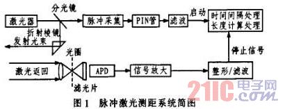
L=ct/2 (1)
It can be known from equation (2) that the time interval precision Δt of the system processing directly determines the ranging accuracy ΔL of the pulse laser ranging system. 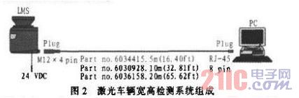
In the first step, the sensor uploads the polar radius (Ï1, Ï2, Ï3, ..., Ïn) of the polar coordinates of the measured sensor to different points of the vehicle under test and the corresponding polar angles (θ1, θ2, θ3, ..., Θn);
(x1=Ï1·cosθ1, y1=Ï1t·sinθ1) (x2=Ï2·cosθ2, y2=Ï2·simθ2) (x3=Ï3·c∞θ3, y3=Ï3·sinθ3) (xn=Ïn·cosθn, Nyn=Ïn·sinθn); 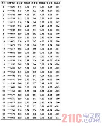
4 Conclusion