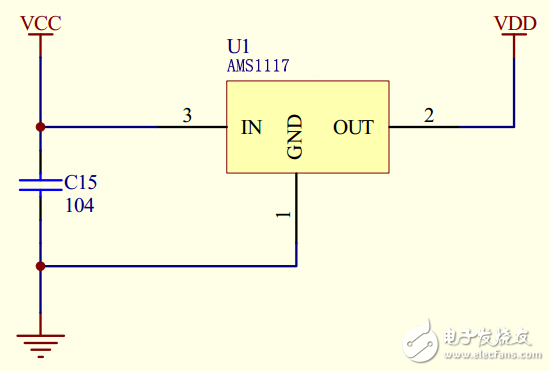
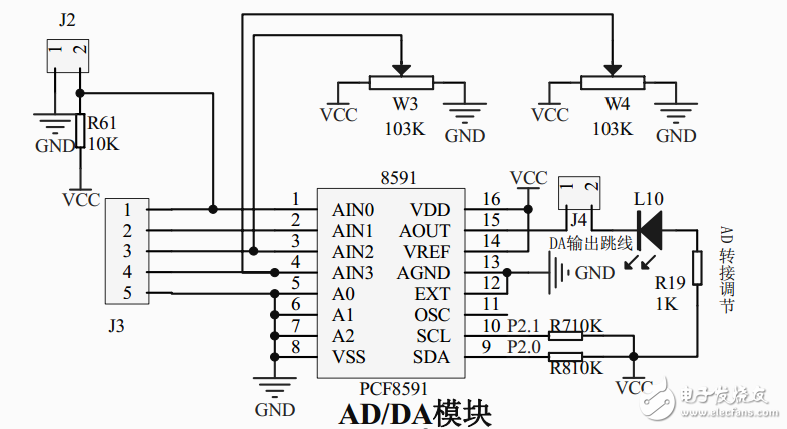
In order to master the development of single-chip microcomputer as early as possible, when we are learning MCU, it is more necessary to choose a suitable MCU development board. After all, it is more difficult to build all the circuits by ourselves. Below we will briefly introduce the relevant knowledge of the circuit diagram identification and purchase of the finished single-chip microcomputer. The finished product development board can be easily purchased from Taobao or the electronics market. There are usually supporting learning materials, especially the examples of programs that can be downloaded directly to the board, which can greatly improve our learning efficiency. 1, the identification of the circuit diagram General product development boards have circuit diagrams, and beginners may have a lot of doubts when looking at circuit diagrams. Below is a partial circuit diagram of a development board. We can see that in order to make the drawing simple and understandable, the circuit diagram of the MCU development board is often drawn into the figure, divided into modules, not all in one picture. Each module is divided according to function, and most of the modules will have VCC and GND labels. In any circuit diagram, all the same reference numerals (such as GND) are connected together in the actual circuit. We can see that the 18th and 19th pins in the minimum system of the MCU are not connected to the crystal oscillator, but the X1 and X2 are marked. In the MCU crystal module, there are also the labels X1 and X2, which means that they are connected together in the actual circuit. 2, power related knowledge The original meaning of GND is ground, which means the voltage 0V reference point. Usually we regard the earth's voltage as 0V. In some circuits, GND is also directly connected to the earth, such as the casing of some household appliances. However, in our MCU circuit, it is not necessary to directly ground it, but still write its label as GND. Learning middle school physics should know that voltage is a relative concept. If we consider the positive pole of a 1.5V battery as 0V, then its negative voltage is -1.5V. Here GND is the 0V voltage point, and the voltage at other points is relative to this 0V. In the figure, the VCC pin of the microcontroller is connected to the VCC label. In this figure, VCC is 5V, which is usually described in the circuit diagram. If we use a 5V power supply to power the circuit, we can connect the negative power supply to GND and the positive terminal to VCC. A circuit does not necessarily have only one type of voltage. In some circuits, different devices require multiple voltages. The most common ones in the microcontroller class are 5V and 3.3V. For example, in the figure below, GND is still 0V, and the VCC number indicates 5V and VDD indicates 3.3V. The 5V voltage is converted to 3.3V by the AMS1117 voltage regulator chip (this is a commonly used voltage regulator chip. This kind of knowledge needs long-term accumulation. If you don't understand it, you can go online to search. For the chip, you can look for the chip manual). A variety of voltages are commonly used for chip conversion, so that the entire circuit only needs to provide one power supply. In some cases, different circuit parts use separate power supply systems (for example, the relay circuit can control the high voltage with a low voltage, and the control terminal is completely isolated from the controlled circuit). 3, some device symbols In the circuit diagram, in addition to the known resistors, capacitors, inductors, diode transistors and other devices, as well as the previously mentioned VCC, GND symbols and various labels, there are some special devices. For example, the block-shaped things like J2 and J3 in the figure are actually ordinary connectors, such as the pin row sockets mentioned above. Because they are not standardized devices, the circuit symbols are usually drawn at random. . There is also a symbol like PCF8591, in fact, like the previous 51, is an integrated circuit, the general circuit diagram will be labeled with the chip model, and then the number of the pin is marked with a number. 4, chip manual When we look at the board's circuit diagram, we find that there are many integrated circuit chips on it. The integrated circuit has also been mentioned many times before. I mentioned earlier that AMS1117 is a commonly used voltage regulator chip, but how do you know how to use this chip? The most accurate and effective way is to check the official information given by the chip manufacturer, which is equivalent to the manual. For the chip, it is the chip manual. Obtaining and viewing the chip manual is one of the basic skills of electronic production. We should learn how to use official materials to learn. All chips will officially give the corresponding DataSheet (databook, chip manual), and some will have ApplicaTIonNote (application note). Since many chips are produced abroad and take into account versatility, the original manuals are often in English. Some large companies will also introduce some Chinese materials, but they are mainly in English. For some common chips, it is easy for us to find translated Chinese manuals and various introduction materials. Generally, these materials were originally tried by others based on the official chip manual. For some less common chips; or to study something more in-depth; or use some of the latest chips, then only official data can be used. The official information is generally typeset. After many revisions, there will be timely errata. For example, TI's ErrataSheet will specifically point out the errors and errors in the official manuals (although some domestic companies do not do well). . Official information is not only easy to find, but also of high quality and authoritative. Non-official materials may be written by people of all levels, many mistypes, quality differences, and errors. Don't be afraid of English. In technical manuals, in addition to some proper nouns, complex sentences, grammar, and incomprehensible vocabulary are avoided. We can understand the proper nouns that we can't understand. Over time, I will get used to it, and the English level will grow up, and I will no longer be afraid of English. Here quoted a classmate's words: "The official documents of large companies are written quite well, easy to understand, and the levels of Chinese translation are different, and the necessary terms do not know what it means. And the Chinese translation of the documents is really bad. I don’t think you are willing to learn English for ten years for a sixth grade?" In general, it is difficult to learn a lot by relying too much on Chinese materials. Of course, for beginners, there is no need to be too demanding. For the commonly used chips at the beginning of the school, the Chinese materials are also very comprehensive. The AMS1117 pdf "AMS1117 Chip Handbook" or "AMS1117 datasheet" can be found online to quickly find the AMS1117 chip manual. We can also find it on some special chip manual websites, and you can also find it on the official website. 5, the choice of development board What is the most suitable development board for learning microcontrollers? We don't need to choose those very expensive and full development boards, but we can't buy the simplest minimum system board. It is best to buy development boards with common modules, such as LCD screens, matrix keyboards, AD/DA, digital tubes, buzzers, etc. In addition, the information on the development board must be complete, especially the program code should be provided. The data is necessary to learn the microcontroller. If you go to buy some electronic devices in the future, in addition to those simple components and commonly used devices that are easy to find on the Internet, you should also ask the seller for the supporting information to facilitate the study, the seller should provide you with supporting materials. Some people may think that the development board is too expensive. In fact, if you are willing to study hard and learn the knowledge, it is a good deal to invest the money for yourself. Normal Electric Test Pen,Screw-Driver With Voltage Tester,Combination Screw Driver Set With Tester,Voltage Detector Tester YINTE TOOLS (NINGBO) CO., LTD , https://www.yinte-tools.com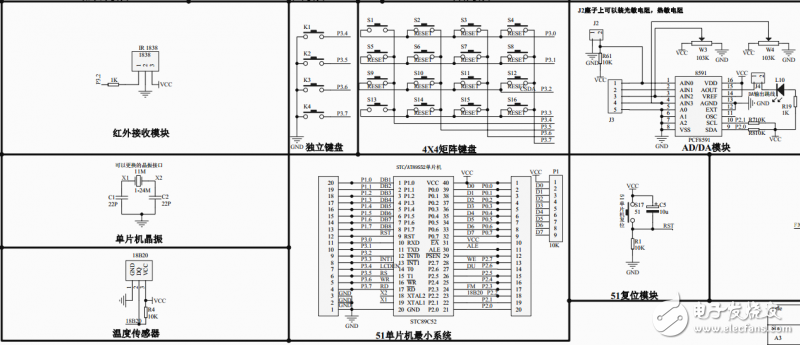
Electronic enthusiast community version of the flying days of the third STC15 microcontroller development board http://z.elecfans.com/75.html solve the four major problems of beginners to learn microcontroller: single-chip performance is not enough, systematic data less, no practical project guidance, no problems People answer, do a good helper for MCU learners