Method for interfacing single chip computer and graphic liquid crystal display
Dot matrix flat panel liquid crystal displays are widely used in various portable devices. Different manufacturers offer a range of core liquid crystal display controllers tailored for specific applications. For instance, Hitachi’s MDF series employs integrated chips such as HD44780, HD61830, HD61202, and T6963C as display controllers. These chips differ in their control logic, instruction sets, and parameter specifications. However, once a flat dot matrix graphic LCD with a built-in control circuit is available, users don't need to worry about the internal chip details. For example, Hitachi's MDF series only requires understanding a few control signals, making it easy to integrate into development projects. The signal configuration remains largely consistent across different models.
This section focuses on the Hitachi MDF5001 160×128 dot matrix graphic LCD, explaining its interface with an 8051 microcontroller and providing sample code for displaying both characters and Chinese characters.
**Introduction to Hitachi MDF5001 160×128 Dot Matrix Graphic LCD**
As shown in Figure 1, this display uses the T6963C controller. It features a 64 KB display buffer and a 128-character dot matrix ROM. The device supports both character and graphics modes, and both can be active simultaneously.
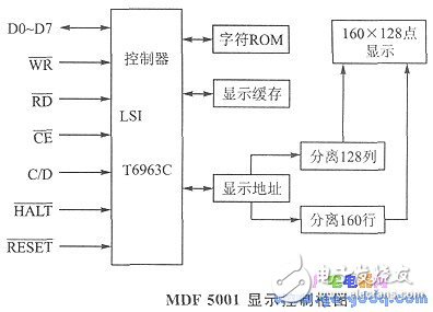
**Control Signals**
- **DO to D7**: 8-bit data lines for communication with the display.
- **WR**: Write signal used to send commands and display data.
- **RD**: Read signal used to read the controller's status and data.
- **CE**: Chip enable signal.
- **C/D**: When writing, a high level indicates a command, while a low level indicates data. During read/write operations, a high level reads the controller status, and a low level reads the data.
- **HALT**: Pauses the LCD operation.
- **RESET**: Resets the LCD operation.
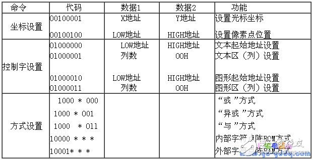
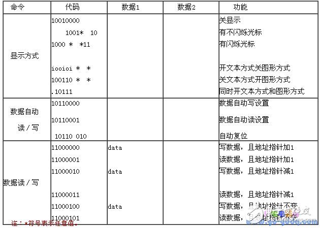
**Control Codes**
The table below lists the display control setup codes.
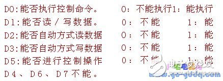
**Display Status Word**
When the control signals are: RD = low, WR = high, CF = low, C/D = high, the data line reflects the current operating state of the display.
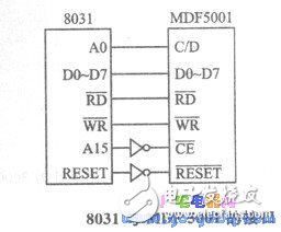
**Interface and Application with the 8031 Microcontroller System**
As illustrated in the figure, under the control of the 8031 microcontroller, the control port (CONP) is addressed at 8000H, and the data port (DATP) is at 8001H. In the initialization routine, the display is set to operate in both text and graphics mode. The LCP subroutine checks the display status and exits once the display is ready for writing.
Car Cigaretter Power Cable,Automobile Display Screen Cable,Car Cigarette Lighter Cable,Car Cigarette Lighter Power Cable
ShenZhen Puchen Electronics Co., Ltd. , http://www.szpuchen.com