**Foreword**
This article presents a "smart detection and control circuit" designed for a water heater using the AT89C2051 microcontroller. The circuit is capable of monitoring the water level in the tank and the operational status of each set of electric heating elements in real time. If an abnormal water level or a fault in the heating element is detected, the system automatically initiates protective actions and issues corresponding sound and light alarm signals to alert maintenance personnel. The design is simple, cost-effective, and easy to implement, making it ideal for practical applications.
**1. Main Functions and Features**
(1) The circuit is built around a single-chip microcontroller (AT89C2051) with only two additional support chips. This minimalistic approach reduces the number of external components, simplifying both manufacturing and operation.
(2) Upon initial power-up, the system checks the water level. If the level is normal (as indicated by the closed water level switch SVV), the three-phase solid-state relay (SSR) is activated, allowing the heating elements to receive power. The system then continuously monitors the water level. If the level drops below the preset minimum (indicating a failure in the automatic water supply system), the SSR is immediately turned off, and a "low water" alarm is triggered through sound and light signals.
(3) While the heating elements are powered, the system monitors their working condition and provides visual feedback via LED indicators on the control panel. When all elements are functioning properly, all three LEDs remain lit. If one element fails, its corresponding LED starts blinking, signaling a fault. In such cases, the water heater can still operate but may require more time to boil. If two or all three elements fail simultaneously, all LEDs flash rapidly, and a buzzer emits a continuous "beep-beep-beep" sound, indicating that immediate repair is necessary.
(4) The temperature switch WK plays a key role in controlling the heating cycle. When WK is closed, it indicates that the water has not yet boiled, and the system activates the SSR, turning on the heating elements and lighting the "heating" indicator. Once the water reaches boiling point, WK opens, and the "insulation" indicator lights up, while the heating elements remain energized to maintain the temperature.
(5) The circuit features optical isolation for both input and output signals, enhancing its resistance to electrical interference and ensuring stable and reliable performance under various conditions.
**2. Circuit Principle**
The circuit is based on the AT89C2051 microcontroller (IC1), which serves as the central processing unit. A simple power-on reset circuit is formed by C3 and R3, while the clock circuit is built using JT, C1, and C2. Only 13 of the 15 I/O ports of IC1 are used. P1.1–P1.6 are connected to LEDs on the control panel, providing visual feedback on the status of the system. P1.7 controls the power to the heating elements via a phototransistor (GO1), which in turn controls the solid-state relays.
P1.0 is used to generate alarm signals. It is connected to IC2, which includes a controllable audio oscillator. When the microcontroller outputs a low signal, the oscillator stops, and no sound is produced. However, when an alarm is needed, the microcontroller sends intermittent high-level signals, causing the oscillator to produce a "beep-beep" sound through the speaker.
For monitoring the status of the heating elements, the circuit uses current transformers (HGQ1–HGQ3) and the TAL420 sensor. These components detect the AC current flowing through the heating elements and convert it into a DC signal that is processed by IC2. The signal is then sent to the microcontroller, allowing it to identify faults and trigger the appropriate LED alerts.
The water level sensor is a float-type switch (SVV) that is connected to GO2. Its output is inverted and fed into the microcontroller’s P3 port, enabling accurate water level detection. Similarly, the temperature switch WK is connected to GO3, and its signal is also processed through an inverter before being read by the microcontroller.
Finally, the power supply is provided by a transformer (T1), a bridge rectifier (QZ), and a 7805 voltage regulator (WY), ensuring a stable +5V DC supply for the entire system.
All-in-one Energy Storage System
An energy storage system (ESS) is a device or set of devices used to store energy for later use. ESSs can store energy in various forms, including chemical, mechanical, thermal, and electrical energy. The stored energy can be used to power homes, buildings, or vehicles, or to supplement the power grid during periods of high demand.

ESSs are becoming increasingly important as renewable energy sources such as solar and wind power become more popular. These sources of energy are intermittent, meaning they only produce electricity when the sun is shining or the wind is blowing. ESSs can help to smooth out these fluctuations in energy production and make renewable energy more reliable and cost-effective.

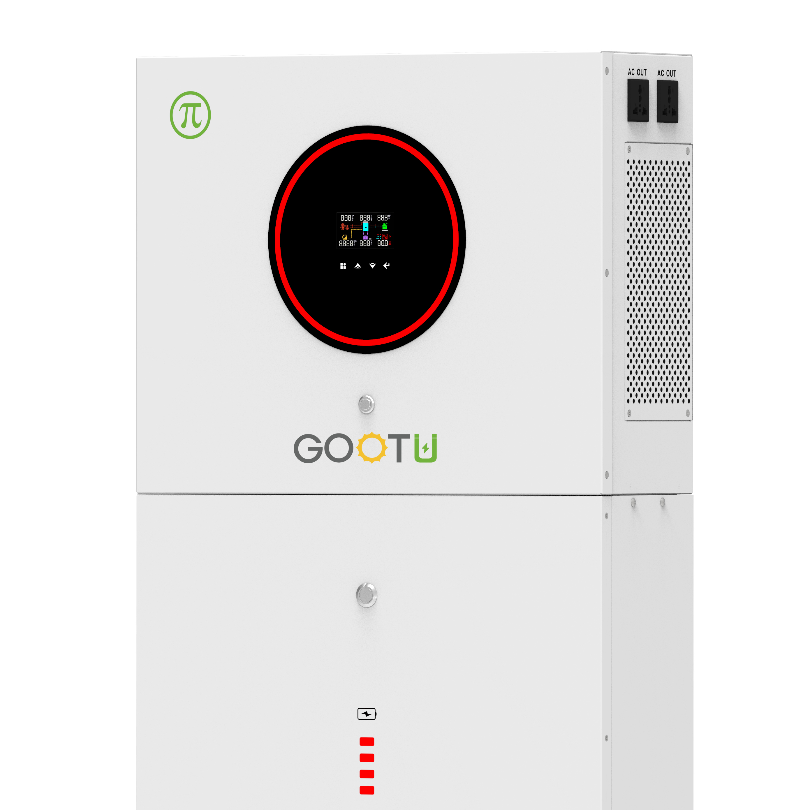
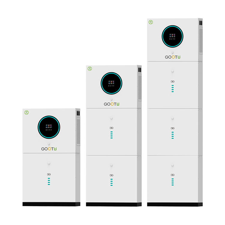
ESS is an integrated battery system that stores your solar energy for backup protection, so when the grid goes down your power stays on. Your system detects outages and automatically recharges with sunlight to keep your appliances running for days.GOOTU offers a modular, flexible design and can be easily customized to meet diverse customer needs.
Energy Storage System,Home Energy Storage System,Modular LiFePO4 Battery,Solar Energy Storage System,Renewable Energy Storage System
Shenzhen Jiesaiyuan Electricity Co., Ltd. , https://www.gootuenergy.com

