Water heater intelligent detection and control circuit designed and manufactured by single chip microcomputer
**Foreword**
This project presents the design and development of a "smart detection and control circuit" for a water heater, utilizing the AT89C2051 microcontroller. The circuit is designed to monitor the water level in the tank and the operational status of each electric heating element in real time. If the water level becomes abnormal or if any of the heating elements malfunction, the system automatically initiates protective measures and provides both visual and audible alarm signals. This allows maintenance personnel to respond promptly and ensure safe and efficient operation. The circuit is characterized by its simple structure, ease of manufacturing, and user-friendly interface.
**1. Main Functions and Features**
(1) The circuit is designed with minimal complexity, using only one microcontroller chip (AT89C2051) and two auxiliary chips, along with a small number of discrete components. All necessary control functions are achieved through this streamlined configuration.
(2) Upon initial power-up, the system checks the water level. Only when the water level is within the normal range—indicated by the closed state of the water level switch SVV—will the three-phase solid-state relay (SSR) be activated, allowing the heating elements to receive power. After that, the system continuously monitors the water level. If the level drops below the preset minimum (indicating a failure in the automatic water supply system), and the SVV switch opens, the system immediately cuts off the power to the heating elements and triggers an audible and visual "water shortage" alarm.
(3) When the heating elements are powered on, the system monitors their working status and provides visual feedback via LEDs on the control panel. If all three sets of heating elements are functioning correctly, all three LED indicators will light up. However, if one set fails, the corresponding LED will blink, signaling a fault. In such cases, the water heater can still operate but may require more time to boil the water. If two or all three sets fail simultaneously, all LEDs will flash, and a buzzer will emit a continuous "beep-beep-beep" sound, indicating a critical failure that requires immediate repair.
(4) The temperature switch WK is used to detect whether the water has been boiled. When it is in the ON position, the water has not yet reached boiling point, and the system activates the SSR to energize the heating elements while lighting the "heating" indicator. Once the water reaches boiling point and WK opens, the "heating" indicator turns off, and the "insulation" indicator lights up, indicating that the system has entered a holding mode.
(5) The circuit features optical isolation at both input and output stages, ensuring strong resistance to electrical interference and reliable performance under various conditions.
**2. Circuit Principle**
The circuit diagram is shown below.
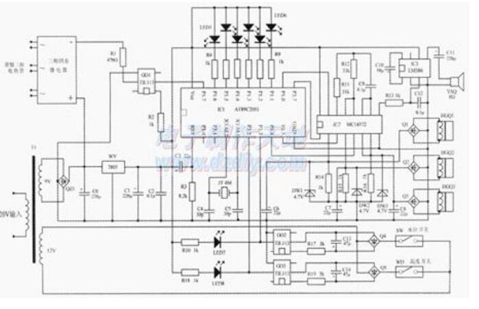
At the heart of the circuit is the AT89C2051 microcontroller (IC1). A simple power-on reset circuit is formed by C3 and R3. The clock circuit is created using the pins of IC1, along with C1, C2, and JT. Out of the 15 I/O ports of IC1, only 13 are used. P1.1–P1.6 serve as output control ports for the LED indicators on the panel, connected through current-limiting resistors. These LEDs are active low, meaning they light up when a low signal is applied. P1.7 is used to control the load (the heating elements), connected to pin 2 of the optocoupler GO1 via a current-limiting resistor. Pin 1 of GO1 is connected to +5V. When P1.7 is high, GO1 and the solid-state relays are turned off, and the heating elements are de-energized. When P1.7 is low, the system powers the heating elements.
P1.0 is the alarm control output port, connected to pin 15 of IC2. IC4, together with external components, forms a controllable audio oscillator. Its 15th pin acts as the control terminal (active high), and the 9th pin is the output. The signal from IC3 is amplified and drives the speaker. Under software control, when P1.0 outputs a low signal, the oscillator stops, and no sound is produced. When an alarm is needed, the software causes P1.0 to output intermittent high-level signals, activating the oscillator and producing a "beep-beep" alarm.
The first seven pins of IC2 form a signal conversion circuit for monitoring the working state of the heating elements. The TAL420 sensor, a vertical core-through type AC current transformer, is mounted directly on the PCB. Each group of heating elements has a corresponding HGQ1–HGQ3 current transformer. When the heating elements are operating normally, an induced AC signal appears at the coil end of each transformer, which is rectified by Q1–Q3 and converted into a DC signal. This signal is then sent to IC2, where it is converted from high to low level and output through pins 1, 3, and 5. These signals are connected to P3.4, P3.5, and P3.7 of the microcontroller.
If a particular heating element fails, the corresponding current transformer will not produce an output, and IC2 will not generate a low-level signal. Combined with software logic, this allows the system to accurately detect and indicate the faulty element via the corresponding LED.
Zener diodes DW1–DW3 protect the current transformer outputs from damage caused by overvoltage. The water level sensor uses a float-type switch that is normally closed. It is connected in series with the control loop of GO2, and the output of GO2 is connected to an inverter circuit, which feeds into P3 of the microcontroller. With software support, the system can accurately determine the water level and trigger the "water shortage" alarm via the corresponding LED. The alarm sound is generated by the same mechanism described earlier, with the software controlling P1.0 to produce intermittent signals.
The temperature sensor uses a temperature switch WK set to 98°C. It is connected to the control loop of GO3, and the output of GO3 is also connected to an inverter circuit, feeding into P3.2 of the microcontroller. This allows the system to accurately detect the temperature state and control the heating elements accordingly, while also providing visual feedback via the "heating" or "insulation" LED.
Finally, the power supply circuit consists of a transformer T1, a bridge rectifier QZ, a 7805 voltage regulator WY, and capacitors C1 and C2. This setup ensures a stable +5V DC power supply for the entire circuit.
LiFePO4 Energy Storage Battery
51.2v lifepo4 lithium battery,battery lithium 15kwh,battery lithium 10kwh,system solar hybrid inverter battery pack,48v lifepo4 battery,lifepo4 battery box,lifepo4 battery solar
Shenzhen Jiesaiyuan Electricity Co., Ltd. , https://www.gootuenergy.com