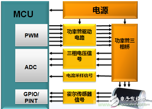
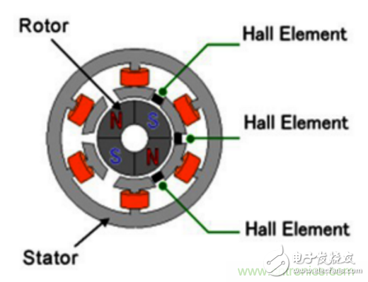
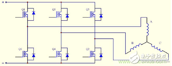
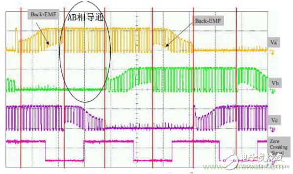
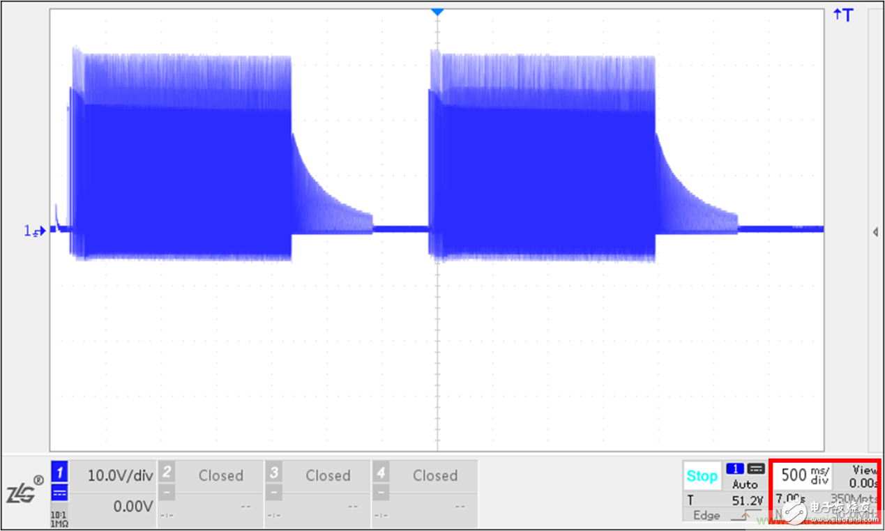
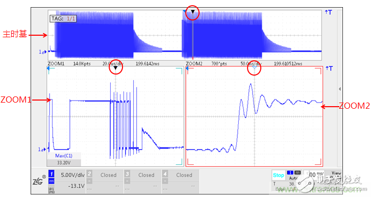
In recent years, brushless motors have been widely used in high-precision control industries such as medical, industrial control, consumer electronics and automotive electronics. The performance of brushless motors depends largely on the motor driver, the development stage, and how engineers can quickly use the oscilloscope. Convenient and realistic analysis of drive signals? This article mainly introduces the typical test and case analysis of the ZDS4054Plus digital excavation oscilloscope for the motor driver. As a "newcomer" in the motor industry, brushless motors are the up-and-coming talents. They are pouring into the high-precision control industry such as medical, industrial control, consumer electronics and automotive electronics. The "brushless" is not the future motor. The development trend of the industry? This article takes the case of a brushless motor in the form of a case! With the development of power electronics and the emergence of new permanent magnet materials, brushless DC motors have been rapidly developed. Brushless DC motors have realized commutation of motors through electronic devices, replacing traditional mechanical brushes and commutators. It consists of a motor body and a driver and is a typical mechatronic product. The stator windings of the motor are mostly made into a three-phase symmetrical star connection, which is very similar to the three-phase asynchronous motor. A magnetized permanent magnet is adhered to the rotor of the motor, and a position sensor is mounted in the motor for detecting the polarity of the rotor of the motor. The driver is composed of power electronic devices and integrated circuits, and functions as: receiving start, stop, and brake signals of the motor to control start, stop, and brake of the motor; receiving position sensor signals and forward and reverse signals for controlling the inverse The power bridges of the transformers are turned on and off to generate continuous torque; the speed command and the speed feedback signal are accepted for controlling and adjusting the speed; providing protection and display. Brushless motors are widely used in medical, industrial control, consumer electronics, power tools, electric vehicles and other fields due to their low noise, long life, high speed, small size, good dynamic performance, large output torque and simple design. First, take a look at the block diagram of the brushless motor driver, as follows: As shown in the figure above, the MCU outputs only six PWM signals through the configuration register. The maximum voltage is only 5V. It cannot directly drive the motor. Instead, it controls the power tube to operate the motor. The driver circuit is usually composed of multiple MOSFETs. The drive axle and the motor drive axle power tube are formed. The commutation of the brushless motor is that the commutation is performed by detecting the position of the rotor. The sense driving method is to detect the rotor position by using the Hall sensor. The non-inductive driving method is to detect and calculate the current during the rotation of the brushless motor. The parameters such as voltage and voltage change, and the rotor position is estimated, and then commutation is performed. The brushless motor is internally equipped with a Hall sensor, which can give an output signal of 1 or 0 according to different magnetic field direction distributions at different positions of the rotor, and the three sensors are evenly installed, and occur 6 times at an electrical angle of 360 degrees. The flip level is 60 degrees electrical angle each time, and the position of the rotor is measured according to the signal coding of the three sensors. This is the commonly used sense drive mode. In addition, the non-inductive driving method is to detect and calculate the parameters such as current and voltage during the rotation of the brushless motor, and to estimate the rotor position, and then perform commutation. Driving circuit simplified diagram In the figure, Q1 to Q6 are power FETs. When the AB phase is required to be turned on, only the Q1 and Q4 tubes need to be opened, and the other tubes are kept off. At this time, the flow path of the current is: positive → Q1 → coil A → winding B → Q4 → negative. The MCU gives the gate of Q1 a PWM signal, and the gate of Q4 is a normally open signal, so you can control the effective voltage of the drive motor by controlling the duty cycle of the PWM signal at the Q1 input. The same is true for the other five-step commutation. The measured phase waveforms are as follows: Actual phase voltage waveform measurement effect What are the new test experiences for the ZDS4054Plus oscilloscope for the PWM signal analysis of the above brushless motor driver? For the driving voltage of the brushless motor in the case, when the engineer observes the PWM signal, if an abnormality occurs in the signal, it is difficult to trigger by the trigger mode. It is necessary to analyze the signal in the envelope by the zoom mode under a large time base. Window observation waveform details), PWM signal frequency is more than tens of K, need to ensure a higher sampling rate, while the PWM signal is also accompanied by current, encoder and other carrier signals, requiring multiple channels to observe separately, from waveform time, sampling rate, In terms of multi-channel and three aspects, large storage is required. Figure 1 shows the PWM drive signal of the brushless motor. When the memory depth is set to 350M, the waveform of 7S is captured, and the sampling rate is still as high as 50M Sa/s, which ensures that the waveform is not distorted. By formula: storage depth = waveform time * sampling rate, the ZDS4000 series oscilloscope comes standard with 512Mpts memory depth, ensuring long-term waveform capture while maintaining high sampling rate. As shown above, after capturing a long time waveform, how to analyze the PWM drive signal or abnormal signal? In addition, in industrial servo applications, under different operating conditions, when switching between different loads, corresponding to different driver waveform changes or abnormal signals, the entire load is switched to a stable process for a long time, and also needs to be in large storage. In depth, watch the waveform details. For the above situation, the ZDS4000 series oscilloscope supports dual ZOOM zoom mode while ensuring large memory depth. You can set the coefficients for the two zoom windows separately, and use the smart label function to be interested in any place. Signals are labeled. In the figure, for the PWM drive signal, the waveform in the main time base is amplified in two ZOOM windows respectively, ZOOM1 is the PWM cycle signal, and ZOOM2 is the oscillation waveform of a certain peak of PWM. Under the guarantee of large storage depth, the sampling rate is 50M Sa /s, to ensure the authenticity of the waveform details. At the same time, with the intelligent labeling function, such as making a label on the main time base, you can quickly find the label points on ZOOM1 and ZOOM2, you can see the label point in ZOOM1 - the third peak of PWM, which can be viewed in ZOOM2. The oscillation and amplitude of the spike. ZDS4000 series digital boring oscilloscope, with 512M deep storage, dual ZOOM mode, template triggering, FIR hardware filtering and intelligent calibration, can quickly and realistically analyze the abnormal waveform of brushless motor driver, which is the waveform of brushless motor industry. Debugging provides the perfect solution! Axial Metallized Polyester Film Capacitors capacitor,Metallized Polypropylene Capacitor,Small Size Capacitor,X-ray Euipment Capacitor XIAN STATE IMPORT & EXPORT CORP. , https://www.capacitorhv.com