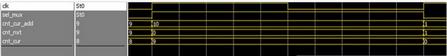
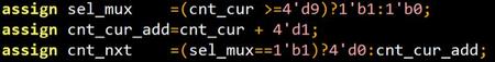
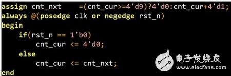
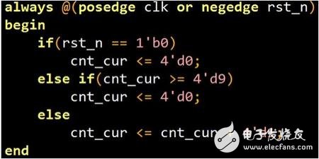
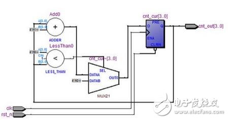
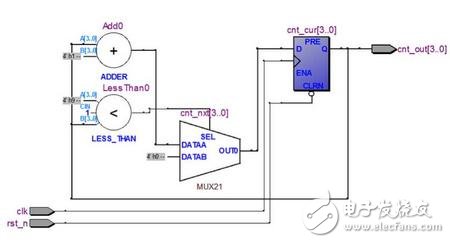
First understand the combinational logic and sequential logic, just to say later, here first talk about the narrow combination of logic and sequential logic, sequential logic generally refers to the D flip-flop, combinational logic refers to: AND gate or gate, the comparator , selectors, encoders, decoders, adders, and of course two types of special ones are tri-state gates and RAM. The sequential logic D flip-flops need to be driven by a clock, that is, they must have a clock to operate. The combinatorial logic does not require a clock driver. The performance on the timing diagram is that the output of the sequential logic is one clock cycle later than the input, while the combined logic input and output are all in the same clock cycle. All digital circuits are composed of combinatorial logic. The sequential logic consists of a large CPU, as small as a spreadsheet chip. Then we look at how the combinational logic and timing logic above are described in hardware description language. 1: with the door Assign c = a&b; Always@(*) c=a&b 2: OR gate Assign c = a|b; Always@(*) c=a|b 3: Africa Assign c = ~a; Always@(*) c=~a 4: Comparator Assign c = (a)=b)? 1'b1:1'b0; Always@(*) If(a)=b) c=1'b1; Else c=1'b0; 5: selector Assign c = (a)=b)? d:e; Always@(*) If(a)=b) c=d; Else c=e; 6: Decoder Always@(*) Case(a) 2'b0;c=4'b0001; 2'b1;c=4'b0010; 2'b2;c=4'b0010; 2'b3; c=4'b1000; Endcase 7: Encoder Always@(*) Case(a) 4'b0001 :c=2'd0; 4'b0010 :c=2'd1; 4'b0010 :c=2'd2; 4'b1000; c=2'd3; Endcase 8: Adder Assign c= a+b; Sequential logic D flip-flop Alway@(posedge clk or negedge rst_n) Begin If(rst_n==1'b0) q "=1'b0; Else q "=d; End Description After completing the above, I can basically describe 90% of the digital circuits with the above standard circuits and languages. Let's start with the simplest counter. Counters are common. Let's write a modulo 10 counter first. Eliminate the module port definition and signal positioning, the following is the core code, in order to let LZ can see the specific circuit, may just look at the code LZ may be somewhat difficult to understand, but it does not matter, to learn the hardware thinking this is a must the road We can see that a simple modulo 10 counter is actually composed of 4 parts, a comparator, an adder, a selector, and 4 D flip-flops, so a counter is actually the one originally introduced above. The basic unit is composed, I opened the FPGA artifact quartus, integrated some, corrected a number of syntax errors, and then the final integrated RTL circuit is as follows The circuit and the code are really good. The code describes the 4 parts of the circuit, and the circuit also shows the 4 parts of the circuit. We can see the ADDER adder, the LESS_THAN comparator, the last D flip-flop of the MUX21 selector. This is hardware thinking. Hardware thinking is that all digital circuits are composed of basic combinational logic and sequential logic components. The written code has corresponding minimum circuit components to correspond to, since the code writes the code. Then, let's take a look at the timing diagram to verify that the input and output of the sequential logic are always delayed by one clock cycle. The input and output of the combinational logic are in the same clock cycle, and the testbench is started. The 10,000 words are omitted here. The waveform finally came out Maybe the picture above the cycle is not necessarily clear, just look at the second picture, we can see These three lines of code are executed at the same time, are serial, and are executed in the clock cycle of cnt_cnr ">=d9, which is the same as the C language, but the assignment of cnt_cur can be seen though Assign cnt_nxt to cnt_cur, but because it is sequential logic, it always delays one clock cycle. The simplest modulo 10 counter is introduced, but not all counters are written so complicated, no, there are Two basic ways of writing, one is written as follows, all the combinational logic is written together. The most common way to write this is to not distinguish between combinatorial logic and sequential logic. All of them are written in an always block and written as sequential logic. This is not an abstraction of the above two circuits. Write, but the basic combinational logic and sequential logic are still the same Do not believe that rtl is exactly the same as above A basic circuit consists of basic combinational logic circuits and D flip-flops. If you can't use two, you may be mistaken. For example, novices often write a delay circuit and can use #10. What, #10 can be composed of a selector, or a NAND or a D flip-flop? The synthesizer can understand it, obviously not, so when you write a code yourself, you must think about what his last circuit is. After talking about the counter, this most commonly used circuit, after talking about this, I want to talk about verilog. My suggestion for verilog is that I encounter blocking logic with combinatorial logic and non-blocking assignment with sequential logic. The basic syntax is So a few, Always assign if else case ? : 》= "= == & | ~ && || ! This is a few, and all the circuits should be described. Others don't have to pay attention to it. You don't need to write RTL. Instead, it will use the wrong, what while, iniTIal, these are used for simulation. Writing rtl is not used at all. As for how to get started faster, the process of FPGA development is nothing more than program, code, simulation, backend constraint, on-board verification, find a project, this process is one step. I believe it should be easy to get started, for example, to develop a simple UART, the most common module, or a dds, or sdram controller, first make the solution, which is to draw the basic circuit and implementation method onto the draft or on the computer, considering various aspects, reliability, and achievability. Resources, can you run to the desired clock frequency, etc. What are the signals of the interface, what is the timing, how is the internal control, the state machine or the counter, what is the state transition diagram of the state machine, and what states? What are the conditions for state transition, will not run, and so on? Alps Tact Switch,Navigation Use Switch,Square Thin Surface Switch,Surface Mount Push Button Switch DA CHENG MINGHUA LIMITED , https://www.alpsswitch.com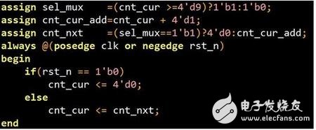
![]()