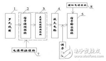
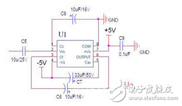
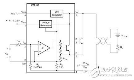
In recent years, with the construction of modern high-voltage and ultra-high-voltage transmission networks, power systems are developing toward large-capacity, high-voltage and high-current, and traditional electromagnetic current transformers for current measurement have been unable to meet their requirements. Under the current, the iron core is easily saturated under the magnetic circuit, which causes a large error in the measurement results. The Rogowski coil transformer has the advantages of wide measuring range, high precision, no magnetic saturation, small volume, etc. It is gradually replacing the traditional electromagnetic current transformer, and has broad application prospects in the power system. This paper introduces the design of a current transducer based on Rogowski coil, real-time measurement of large AC current in the power grid. The transmitter uses XTR115 chip to convert the voltage signal generated by Rogowski coil into current signal and output DC 4~20mA current signal. . Working principle and design The Rogowski coil is a hollow inductor formed by uniformly winding a wire around a non-magnetic skeleton of a circular section. The Rogowski coil is used as a sensing head for current measurement in the power grid, and a wire having a large current is passed vertically through the center of the coil. Electromagnetic induction is generated to induce a voltage signal of the magnitude of the current being measured. The voltage signal generated by the Rogowski coil is connected to the signal conditioning module for signal processing, and finally the industrial standard signal DC4-20mA is output. The circuit design framework is shown in Figure 1. Signal conditioning circuit The signal conditioning circuit implements an isolated input to the input signal, including signal filtering, rectification circuitry, and signal integration circuitry. The circuit mainly uses the RC filter for the induced voltage output of the Rogowski coil, and then is connected to the input pin of the dual-supply op amp chip after being divided by the resistor, and the operational amplifier is used to form an approximate integrator, and the device parameters are selected reasonably. The sensor's measurement sensitivity, accuracy and signal response bandwidth are guaranteed. True rms conversion circuit The true RMS conversion circuit realizes the AC/DC true RMS conversion in the circuit, and converts the input AC signal into a true RMS DC voltage through the true RMS chip, and can accurately measure the effective value of various voltage waveforms without being considered Measure the parameters of the waveform as well as the distortion. As shown in Figure 2: In the circuit, the Ui signal is directly separated by the capacitor C5 and input into the true RMS chip. The function of the capacitors C8 and C9 is to filter out the high-frequency interference in the circuit. True RMS work requirements. amplifying circuit The function of the amplifying circuit is to properly amplify the voltage signal outputted by the true RMS conversion circuit after passing through the RC filter circuit, and adopt an op amp chip to adjust the amplification parameter in the circuit while satisfying the zero point output power consumption requirement, so that the circuit finally The output can reach full scale rating. Signal output circuit The signal output circuit mainly adopts the precision current transfer chip XTR115 produced by TI Company, which has the advantages of high precision, low power consumption of the chip and small nonlinear error. The internal 2.5V reference voltage is generated, and the internal precision voltage regulator with +5V is provided. The device can be powered separately from an external circuit (such as an amplifier in the circuit), simplifying the design of the external power supply, as shown in Figure 3. Adopt XTR115 chip design, it is necessary to strictly control the power consumption of the current, to ensure that the power consumption of the transmitter itself (all the circuits including the sensor) is not more than 3.5mA, and the zeroing circuit is set in front of the XTR115 as the zero point adjustment of the transmitter. , so that the transmitter guarantees a zero output of 4mA. Anti-interference measures The current transmitter uses the current signal as the transmission signal and has high anti-interference ability. However, due to the long transmission distance and the complexity of the industrial site, electrical isolation and anti-interference measures should be considered in the design. The Rogowski coil transmitter designed in this paper uses a power isolation module to reduce ripple interference and improve system reliability. At the same time, a diode is connected in series at the input end of the power supply for reverse polarity protection. The layout of the device to reduce interference signals.
This brush is 2 In 1 Small Brush. It's a very special brush. It is small and cute. Its the aggregation with crevice nozzle and fur brush. This 2 in 1 aggregation let cleaning is more easy. You can easily remove dust edge horn corners those are difficult to clean. So people will effortlessly clean the house,they will be more happy. This brush also can be use by people to clean the computer,keyboard,sofa,bed and so on. It's a very useful brush. It also can clean the dust in the corner. It become the crevice nozzle to clean. How useful it is,hope you will like it. Now let's see the picture blow.
2 In 1 Small Brush 2 In 1 Small Brush, Folding Brush, Small Cleaning Brush, Small Hand Brush Ningbo ChinaClean Household Appliances Manufacture Co., Ltd. , https://www.chinaclean-elec.com